
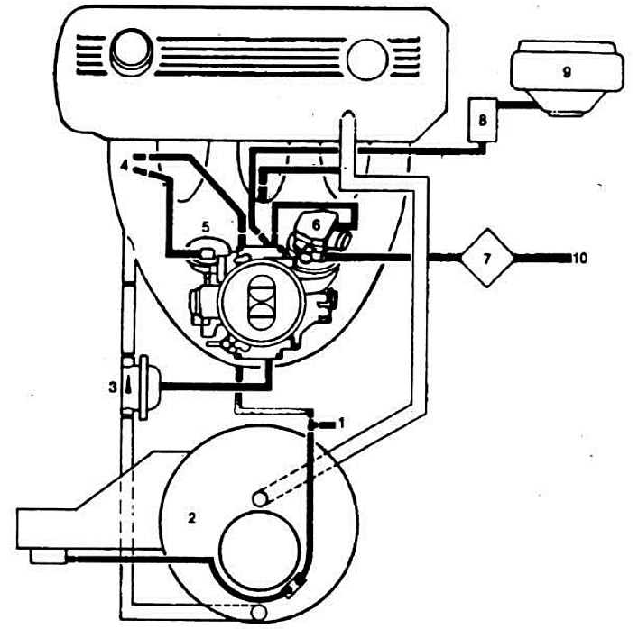
Air route diagram:
1 — place of connection of the block of the temperature sensor in the cabin (on cars with electronic heating system); 2 - air filter; 3 — air valve of the engine braking system (intake manifold vacuum limiter); 4 - damper of the 2nd chamber; 5 — 2nd chamber diaphragm type pneumatic actuator; 6 — 1st chamber throttle valve servo drive; 7 — filter with atmospheric valve of throttle valve servo drive of 1st chamber; 8 — electromagnetic valve for adjusting ignition timing; 9 - vacuum regulator (actuator engine) ignition distributor sensor; 10 — supply of atmospheric pressure to the throttle valve servo drive of the 1st chamber from the vehicle interior.
(The original article is located on BMWMan.ru)