
The control unit regulates the injection time and thus the amount of injected fuel in accordance with the measured air mass. With a longer opening of the nozzle, more fuel is injected. Additional sensing elements and sensors ensure the supply of the right amount of fuel even in extreme driving situations.
The start valve injects additional fuel into the intake manifold to help start the engine.
The thermal time switch determines the duration of injection by the cold start injector.
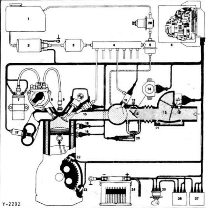
Diagram of the Motronic injection device
1 fuel tank
2 Electric fuel pump
3 Fuel filter
4 distribution tube
5 Pressure regulator
6 Control unit
7 Ignition coil
8 High voltage ignition distributor
9 spark plug
10 Nozzle
11 Start valve
12 Idle speed adjusting screw
13 Throttle valve
14 Throttle switch
15 Air mass meter
16 Intake air temperature sensor
17 Lambda probe
18 Thermal time switch
19 Engine temperature sensor
20 Idle speed regulator
21 Adjusting screw for CO content
22 Reference mark sensor
23 Speed sensor
24 Battery
25 Ignition switch
26 Main relay
27 Fuel pump relay
28 Vibration damper