
- Home
- BMW 3 Series
- E36
- Electrical equipment
- Electrical circuits
- Using Electrical Schematics
Using Electrical Schematics (BMW 3 Series E36)
Electrical diagrams are necessary when detecting faults in electrical equipment and when installing additional equipment. The diagrams show the passage of signals and the laying of cables. The corresponding current circuit must be closed, otherwise no electric current will flow through this circuit. For example, it is not enough to supply only positive voltage to the headlights without simultaneously connecting them to ground.
Therefore, the ground wire from the battery is connected to the body. However, this connection to the ground is often insufficient, and the corresponding consumer is connected to the ground directly by a ground wire, the insulation of which is usually brown. Relays, switches, fuses, measuring elements, electric motors and other electrical elements are included in separate current circuits. For their correct connection, these elements have markings on their contacts.
To organize the interlacing of wires in electrical diagrams, individual current circuits are arranged vertically on the diagrams and numbered. Interacting electrical elements are depicted on one common diagram.
As a rule, the upper part of the electrical diagram shows the connections of the current circuits to the positive power supply, while the lower part of the diagram shows the connections to the ground. The connection to the ground is usually made by connecting the housing of the unit to the body, but in some cases the ground can be supplied through a separate wire from the ground point on the body.
The most important terminals are designated as follows: Terminal 15 is written through the ignition switch. Voltage is present on the terminal only after the ignition is turned on. The wires are usually black or black with colored stripes.
Terminal 30. Battery voltage is always present on this terminal. The wires are usually red or red with colored stripes.
Terminal 31 is connected to ground. Ground wires are mostly brown.
Since the original electrical diagrams for all BMW 3 Series models take up about 1000 pages, the diagrams provided here are limited to the 316i, 318i and 325td models. New editions publish the current electrical diagram, which can also be used by owners of older models.

Relay board under the dashboard on the left.
The original material is located on the website: bmwman
Therefore, the ground wire from the battery is connected to the body. However, this connection to the ground is often insufficient, and the corresponding consumer is connected to the ground directly by a ground wire, the insulation of which is usually brown. Relays, switches, fuses, measuring elements, electric motors and other electrical elements are included in separate current circuits. For their correct connection, these elements have markings on their contacts.
To organize the interlacing of wires in electrical diagrams, individual current circuits are arranged vertically on the diagrams and numbered. Interacting electrical elements are depicted on one common diagram.
As a rule, the upper part of the electrical diagram shows the connections of the current circuits to the positive power supply, while the lower part of the diagram shows the connections to the ground. The connection to the ground is usually made by connecting the housing of the unit to the body, but in some cases the ground can be supplied through a separate wire from the ground point on the body.
Note: The images of the elements and wires are not to scale. For example, a wire longer than 1 m is shown as a line of several centimeters.
The most important terminals are designated as follows: Terminal 15 is written through the ignition switch. Voltage is present on the terminal only after the ignition is turned on. The wires are usually black or black with colored stripes.
Terminal 30. Battery voltage is always present on this terminal. The wires are usually red or red with colored stripes.
Terminal 31 is connected to ground. Ground wires are mostly brown.
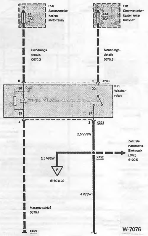
- Switches are always shown in a de-energized state; here for example, K11.
- A dashed border around a schematic element means that the element is shown in full; here for example, K11.
- The dashed line between pin 8 and pin 6 on the X293 connector means that both pins belong to the X293 connector.
- The dashed line from fuse F1 to contact 8 of connector X293 represents the positive power supply from relay K11.
- The dashed line with an arrow at the X452 connector indicates that there are multiple wires connected to the X452 connector.
- The dashed line from contact 4 of connector X293 to ground point X493 displays the ground supply from relay K11.
- The solid line from connector X452 with the letter A in the open arrow indicates the current loop where this current path continues. The interruption of the 4 VI/SW wire from connector X452 by the wavy line indicates that the wire continues on the next circuit diagram.
Electrical diagrams
Since the original electrical diagrams for all BMW 3 Series models take up about 1000 pages, the diagrams provided here are limited to the 316i, 318i and 325td models. New editions publish the current electrical diagram, which can also be used by owners of older models.
Conventional designations
- Batterie - Accumulator
- Safety - Fuse
- Fusible links - Fusible links
- Automatic fuse - Automatic fuse
- Magnetspule - Electromagnet coil
- Magnetventil - Electromagnetic valve
- Widerstand - Resistance
- Heizelement - Heating element
- Loudspeaker or signal - Loudspeaker or sound signal
- Gluhlampe - Incandescent lamp
- Permanent magnet motor single speed - Permanent magnet motor single speed
- Permanent magnet motor two-speed - Permanent magnet motor two-speed
- Potentiometer The motor moves due to an external force - Potentiometer. The motor moves due to an external force
- Potentiometer Change in resistance due to pressure or temperature changes - Potentiometer. Change in resistance due to pressure or temperature changes
- Diode Current flows in the direction of the arrow
- Z-Diode for voltage regulation - Zener diode for voltage regulation
- Light-emitting diode - Light-emitting diode
- Lambdasonde - Lambda probe
- Zundspule - Ignition Coil
- Steuer-/Leistungselektronik - Electronic control/amplification circuit
- Radio - Radio receiver
- Transistorschalter - Transistor key
- Klopfsensor - Knock Sensor
- Heizelement - Heating element
- Gesamtes Bauteil - The whole element
- Part of an Element - Part of an Element
- Threaded fastening element - Element with threaded fastening
- Body of the element directly connected to the vehicle mass - Body of the element directly connected to the vehicle mass
- Connector plugged into element - Connector plugged into element
- Connector connected to the element connection wire - Connector connected to the element connection wire
- Single-pole switch - Single-pole switch
- Double pole switch The dashed line indicates the mechanical connection between the switches - Double pole switch. The dashed line indicates the mechanical connection between the switches
- Fuse connected in a current circuit - A fuse connected in a current circuit
- single-color insulation - single-color wire insulation
- Stiftnummer - pin number
- Connector Number in the List of Elements - Connector serial number in the list of elements
- Leitungsisolation mit Farbstreifen (Griin und Weib) - Insulation with colored stripes (green and white)
- Wavy lines indicate the continuation of the wire - A wavy line indicates the continuation of the wire
- Two pins in a dense connector - Two pins in a single connector
- Strichlinie bezeichnet AnschluBpunkte desselben Steckverbinders-Dashed line indicates the connection points of a single connector
- An Karrosseriteil befestigte Leitung (MasseanschluB) - Wire fixed to the body (ground connection)
- Mass connection number in the list of elements - Mass connection serial number in the list of elements
Figure W-7076
- Stromverteilerkasten Motorraum - Distribution box in the engine compartment
- Electrical distribution box under the rear seat - Distribution box under the rear seat
- Fuse box diagram details - Fuse box diagram details
- Wischerrelais - Windscreen wiper relay
- Central Body Electronics (ZKE) - Central Body Electronics (ZKE)
- MasseanschluB - Mass connection
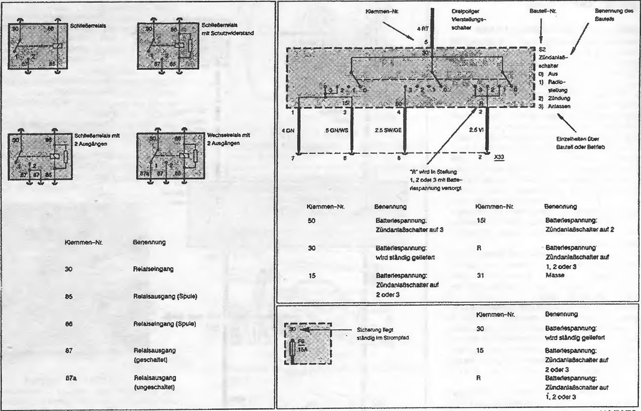
Figure W-7079
- SchlieBer-Relais - Connection relay
- Connection relay with protective resistance - Connection relay with protective resistance
- Switching relay with 2 outputs - Switching relay with 2 outputs
- Switching relay with 2 outputs - Switching relay with 2 outputs
- Three-pole switch - Three-pole switch
- Klemmen-Nr. - Terminal number
- Bauteil Nr. - Item No
- Element Name - Element Name
- Switch 0 = Off 1 = Radio position 2 - Ignition 3 - Starter - Ignition switch 0 = Off 1 - Radio position 2 - Ignition 3 - Starter
- Details about the element and its function - Details about the element and its function
- "R" wird in Stellung 1,2 oder 3 mit Batteriespannung versorgt - The battery voltage is applied to "R" in positions 1,2 or 3
- The fuse is permanently in the current circuit - The fuse is permanently in the current circuit
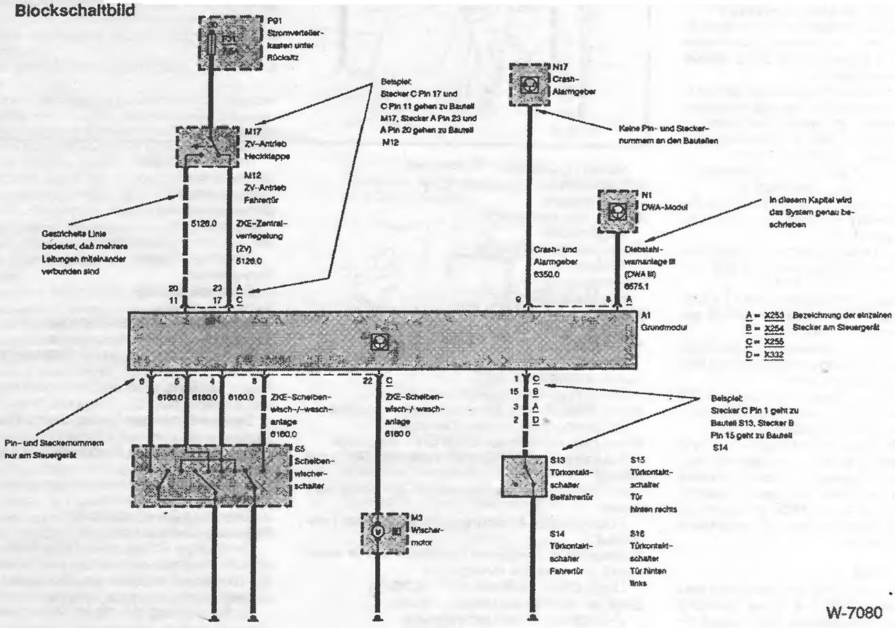
Figure W-7080
- Distribution box under the rear seat - Distribution box under the rear seat
- Crash-Alarmgeber - Crash-alarm sensor
- Example: Connect C Pin 17 and C Pin 11 to connector M17, Connect A Pin 23 and A Pin 20 to connector M12 - Example: Pin 17 of connector C and pin 11 of connector C go to element M17, pin 23 of connector A and pin 20 of connector A go to element M12
- ZV-Antrieb Heckklappe - Drive for the central locking system of the luggage compartment lid
- ZV-Antrieb-Fahrertur - Centrally controlled locking system drive for driver's door
- ZKE-Zentralverriegelung - Centrally controlled locking system
- Gestrichelte Linie bedeutet, daB mehrere Leitungen miteinander verbunden sind-A dashed line means that several wires are connected.
- No pin numbers and connector designations - The components do not have pin numbers or connector designations
- DWA-Modul - Security alarm system module
- In this section the system is described in detail - The system is described in detail in this section
- Alarm System III (DWA III) - Alarm System III (DWA III)
- Designation of individual connectors on the control unit - Designation of individual connectors on the control unit
- Pin and connector numbers are indicated only on the control unit
- ZKE-Windscreen wiper/washer system - Windscreen wiper and washer system
- Windscreen wiper switch - Windscreen wiper switch
- Wischermotor - Washer motor
- Front passenger door contact switch - Front passenger door contact switch
- Driver's door contact switch - Driver's door contact switch
- Turkontaktschalter Tur hinten rechts-Rear right door contact switch
- Tuirkontaktschalter Tur hinten links-Rear left door contact switch
- Example: Connector C with Pin 1 to element S13, Connector B with Pin 15 to element S14 - Example: Pin 1 of connector C goes to element S13, Pin 15 of connector B goes to element S14. Distribution boxes
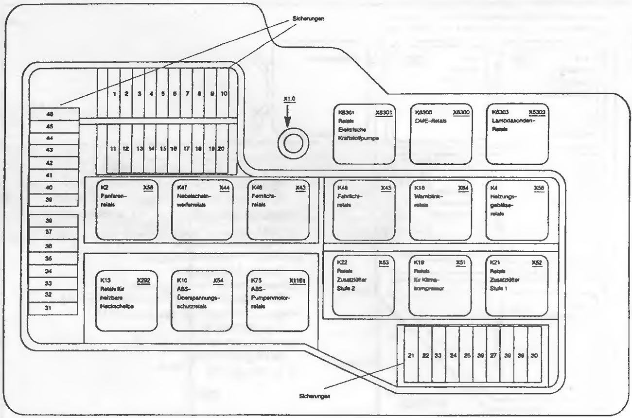
Figure W-7081
- Fuses - Fuses
- Electric Fuel Pump Relay - Electric Fuel Pump Relay
- DME-Relay - relay
- DME Lambda Probe Relay - Lambda Probe Relay
- Fanfarenrelais - Fanfare relay
- Nebelscheinwerferrelais - Fog light relay
- Fernlichtrelais - High beam relay
- Low beam relay - Low beam relay
- Wamblinkrelais - Alarm relay
- Heating Fan Relay - Heating Fan Relay
- Heated Rear Window Relay - Heated Rear Window Relay
- ABS-Overload Protection Relay - ABS Overload Protection Relay
- ABS-Pumpenmotorrelais - ABS pump motor relay
- Relay Additional Fan Stage 2 - Relay Additional Fan Stage 2
- Relay for Klimakompressor - Air conditioning compressor relay
- Relay Additional Fan Stage 1 - Relay Additional Fan Stage 1
Figure W-7082
Relay board under the dashboard on the left.
- Relaisbox Stand heating/stand-off - Relay box for heating and ventilation in the parking lot
- Doppelrelaismodul - Double relay module
- Crash-Alarmgeber - Crash-alarm sensor
- Headlamp cleaning system module (SRA) - Headlamp cleaning system module (SRA)
- Komfortrelais - Comfort relay
- nichtgebraucht - not used
Wire color designations
- BL - blue
- BR - brown
- GE - yellow
- GN - green
- OR - orange
- RS - pink
- RT - red
- SW - black
- VI - purple
- WS - white
- TR - transparent
The original material is located on the website: bmwman
This article is available at russian, bulgarian, belarusian, ukrainian, serbian, croatian, romanian, polish, slovak, hungarian
Article verified: Chebotarev Vladislav
Share information:
Previous articles
БМВ E36: Electrical circuits
Next articles
Similar articles on other types of BMW cars:
Electrical diagram of cars «518», «520», «520A» and «520i» BMW 5 Series E12 (1972-1981)
Checking electrical connections BMW 5 Series E34 (1988-1996)
Electrical equipment. General information BMW 7 Series E32 (1986-1994)
Engine Electrical System Specifications BMW 7 Series E38 (1994-2001)
Connecting electrical appliances BMW X3 E83 (2003-2010)
Checking electrical systems BMW X5 E53 (1999-2006)
Link in different formats to this page
Visitor comments
No comments yet
- General information
- Manual
- Maintenance
- Power unit
- Engine repair
- Cooling system
- Power system (gasoline)
- Injection system (gasoline)
- Fuel system (diesel)
- Exhaust system
- Ignition system
- Charge and launch systems
- Transmission
- Car gearbox
- Clutch and drive shafts
- Chassis
- Brake system
- Suspension front and rear
- Steering
- Body
- Body care and repair
- Exterior
- Interior
- Electrical equipment
- Troubleshooting
- Lighting and signaling
- Equipment and devices
- Heater and air conditioner
- Electrical circuits
- General information
- Manual
- Repair on the road
- Weekly checks
- Maintenance
- Troubleshooting
- Power unit
- 4 cylinder engines
- 6 cylinder engines
- Engine overhaul
- Cooling and heating
- Fuel and exhaust system
- Starting and charging system
- Ignition system
- Transmission
- Clutch
- Mechanical gearbox
- Automatic gearbox
- Cardan and drive shafts
- Chassis
- Brake system
- Wheel suspension
- Steering
- Body
- Exterior
- Interior
- Electrical equipment
- Equipment and devices
- Electrical circuits
- General information
- Maintenance
- Power unit
- Engine repair
- Cooling system
- Ignition system
- Supply system
- Fuel injection system
- Exhaust system
- Transmission
- Clutch
- Car gearbox
- Front and rear axle
- Chassis
- Steering
- Brake system
- Body
- Exterior
- Interior
- Electrical equipment
- Heating system
- Equipment and devices
- Power devices
- Electrical circuits
- Power unit
- M10/M20 engine
- M40 engine
- Ignition system
- Lubrication system
- Cooling system
- Supply system
- Fuel injection
- Exhaust system
- Transmission
- Clutch
- Manual gearbox
- Front axle
- Rear axle
- Chassis
- Steering
- Brake system
- Body
- Exterior
- Interior
- Electrical equipment
- Heating system
- Equipment and devices
- Electrical circuits
- General information
- Specifications
- Operation and maintenance
- 4-cylinder engine
- Engine repair
- Cooling and lubrication system
- Supply system
- Ignition system
- 6-cylinder engine
- Engine repair
- Cooling and lubrication system
- Supply system
- Fuel injection system
- Ignition system
- Transmission
- Clutch
- 4-speed manual gearbox
- 5-speed manual gearbox
- Automatic gearbox
- Cardan and rear axle
- Chassis
- Steering
- Front suspension
- Rear suspension
- Brake system
- Electrical equipment
- Equipment and devices
- Electrical circuits