
- Home
- BMW 3 Series
- E21
- 6-cylinder engine
- Fuel injection system
- Features of the device and operating principle
Features of the device and operating principle (BMW 3 Series E21)
The fuel pump takes fuel from the fuel tank and delivers it through the filter and accumulator to the fuel distributor.
The amount of air sucked into the intake manifold is measured by the air flow meter.
The air flow meter is installed before the throttle valve. It is equipped with a guide device with a pressure disk fixed on a movable lever, which deflects depending on the air flow. The displacement of the pressure disk of the air flow meter is transmitted through the lever to the distributor plunger of the distributor, which determines the amount of fuel in the system.
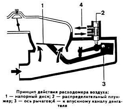
The fuel quantity distributor, in addition to the distribution plunger, includes a supply pressure regulator, a differential pressure valve, a fuel supply line and six injection nozzles in accordance with the number of engine cylinders. When the air flow meter pressure disk rises, the distribution plunger of the fuel quantity distributor moves accordingly, opening with its control edges access of fuel to the upper chamber of the differential pressure valve, separated from the lower chamber by a diaphragm. The fuel pressure and the force of the spring acting on the upper surface of the diaphragm are greater than the pressure on the lower surface of the diaphragm. As a result, the diaphragm moves downwards and opens the fuel supply channels to the nozzles.
The supply pressure regulator maintains the fuel pressure in the system at a certain level and ensures that excess fuel is supplied to the drain line.
The fuel filter is designed to clean the fuel circulating in the system.
The fuel accumulator is installed behind the fuel pump. It has a damper and accumulator chambers, which are separated by a diaphragm.
An additional partition with a disc valve is located in front of the diaphragm, providing fuel supply to the system. A throttling hole for fuel draining is made in the partition.
After the fuel pump is turned on, the storage chamber is filled with fuel and the spring diaphragm is stretched to the stop. After the engine is stopped, due to the tension of the diaphragm, the fuel remains under pressure and the formation of fuel vapor is not allowed, which facilitates the start of a hot engine.
To ensure engine start and warm-up, the K-Jetronic injection system includes an electromagnetic starting injector, an additional air supply valve and a control pressure regulator (heating corrector).
This injector is designed to inject an additional amount of fuel into the intake manifold when starting a cold engine. It works in conjunction with a thermal time relay, which controls its electrical circuit depending on the engine temperature and the duration of its start.
This valve serves to increase the crankshaft speed during engine warm-up. When starting a cold engine, the additional air supply channel is opened by the rotary valve flap, which moves when the bimetallic spring heats up. As it warms up, the additional air supply channel gradually closes.
In addition, the supply of additional air is regulated by the pressure disk of the air flow meter, the movement of which leads to a corresponding rise of the distribution plunger, which also contributes to an increase in the crankshaft speed (with the throttle valve closed).
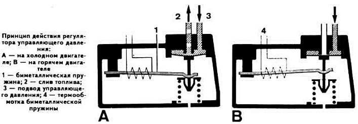
This unit enriches the working mixture entering the combustion chambers when the engine is warming up. When the engine is cold, the bimetallic spring compresses the diaphragm valve spring, opening the fuel drain channel. which leads to a decrease in the counteraction on the distribution plunger. A decrease in the control pressure with constant air flow causes an increase in the stroke of the pressure disk. As a result, the distribution plunger is additionally lifted, increasing the amount of fuel supplied to the injectors.
As the bimetallic spring heats up, the pressure on the spring of the diaphragm valve of the control pressure regulator decreases and the drain channel slowly closes. The control pressure reaches the normal value and enrichment of the combustible mixture stops.
(The original version is on the portal «www.bmwman.ru»)
The amount of air sucked into the intake manifold is measured by the air flow meter.
The air flow meter is installed before the throttle valve. It is equipped with a guide device with a pressure disk fixed on a movable lever, which deflects depending on the air flow. The displacement of the pressure disk of the air flow meter is transmitted through the lever to the distributor plunger of the distributor, which determines the amount of fuel in the system.
The fuel quantity distributor, in addition to the distribution plunger, includes a supply pressure regulator, a differential pressure valve, a fuel supply line and six injection nozzles in accordance with the number of engine cylinders. When the air flow meter pressure disk rises, the distribution plunger of the fuel quantity distributor moves accordingly, opening with its control edges access of fuel to the upper chamber of the differential pressure valve, separated from the lower chamber by a diaphragm. The fuel pressure and the force of the spring acting on the upper surface of the diaphragm are greater than the pressure on the lower surface of the diaphragm. As a result, the diaphragm moves downwards and opens the fuel supply channels to the nozzles.
The supply pressure regulator maintains the fuel pressure in the system at a certain level and ensures that excess fuel is supplied to the drain line.
Auxiliary elements of the fuel injection system
The fuel filter is designed to clean the fuel circulating in the system.
The fuel accumulator is installed behind the fuel pump. It has a damper and accumulator chambers, which are separated by a diaphragm.
An additional partition with a disc valve is located in front of the diaphragm, providing fuel supply to the system. A throttling hole for fuel draining is made in the partition.
After the fuel pump is turned on, the storage chamber is filled with fuel and the spring diaphragm is stretched to the stop. After the engine is stopped, due to the tension of the diaphragm, the fuel remains under pressure and the formation of fuel vapor is not allowed, which facilitates the start of a hot engine.
Cold engine starting and engine warming up
To ensure engine start and warm-up, the K-Jetronic injection system includes an electromagnetic starting injector, an additional air supply valve and a control pressure regulator (heating corrector).
Electromagnetic starting nozzle
This injector is designed to inject an additional amount of fuel into the intake manifold when starting a cold engine. It works in conjunction with a thermal time relay, which controls its electrical circuit depending on the engine temperature and the duration of its start.
Additional air supply valve
This valve serves to increase the crankshaft speed during engine warm-up. When starting a cold engine, the additional air supply channel is opened by the rotary valve flap, which moves when the bimetallic spring heats up. As it warms up, the additional air supply channel gradually closes.
In addition, the supply of additional air is regulated by the pressure disk of the air flow meter, the movement of which leads to a corresponding rise of the distribution plunger, which also contributes to an increase in the crankshaft speed (with the throttle valve closed).
Control pressure regulator
This unit enriches the working mixture entering the combustion chambers when the engine is warming up. When the engine is cold, the bimetallic spring compresses the diaphragm valve spring, opening the fuel drain channel. which leads to a decrease in the counteraction on the distribution plunger. A decrease in the control pressure with constant air flow causes an increase in the stroke of the pressure disk. As a result, the distribution plunger is additionally lifted, increasing the amount of fuel supplied to the injectors.
As the bimetallic spring heats up, the pressure on the spring of the diaphragm valve of the control pressure regulator decreases and the drain channel slowly closes. The control pressure reaches the normal value and enrichment of the combustible mixture stops.
(The original version is on the portal «www.bmwman.ru»)
This article is available at russian, bulgarian, belarusian, ukrainian, serbian, croatian, romanian, polish, slovak, hungarian
Article verified: Polikarpov Saveliy
Share information:
Previous articles
БМВ E21: Fuel injection system
Next articles
Similar articles on other types of BMW cars:
Features of the controller device BMW 5 Series E12 (1972-1981)
Operating principle of the Motronic DME M1.1 and M1.7 system BMW 5 Series E34 (1988-1996)
Diagnostic device memory BMW 7 Series E32 (1986-1994)
Controls and operating techniques BMW 7 Series E38 (1994-2001)
Rear window heating device BMW X3 E83 (2003-2010)
Features of winter operation of a diesel engine BMW X5 E53 (1999-2006)
Features of the controller device BMW 5 Series E12 (1972-1981)
Operating principle of the Motronic DME M1.1 and M1.7 system BMW 5 Series E34 (1988-1996)
Diagnostic device memory BMW 7 Series E32 (1986-1994)
Controls and operating techniques BMW 7 Series E38 (1994-2001)
Rear window heating device BMW X3 E83 (2003-2010)
Features of winter operation of a diesel engine BMW X5 E53 (1999-2006)
Link in different formats to this page
Visitor comments
No comments yet
- General information
- Manual
- Maintenance
- Power unit
- Engine repair
- Cooling system
- Power system (gasoline)
- Injection system (gasoline)
- Fuel system (diesel)
- Exhaust system
- Ignition system
- Charge and launch systems
- Transmission
- Car gearbox
- Clutch and drive shafts
- Chassis
- Brake system
- Suspension front and rear
- Steering
- Body
- Body care and repair
- Exterior
- Interior
- Electrical equipment
- Troubleshooting
- Lighting and signaling
- Equipment and devices
- Heater and air conditioner
- Electrical circuits
- General information
- Manual
- Repair on the road
- Weekly checks
- Maintenance
- Troubleshooting
- Power unit
- 4 cylinder engines
- 6 cylinder engines
- Engine overhaul
- Cooling and heating
- Fuel and exhaust system
- Starting and charging system
- Ignition system
- Transmission
- Clutch
- Mechanical gearbox
- Automatic gearbox
- Cardan and drive shafts
- Chassis
- Brake system
- Wheel suspension
- Steering
- Body
- Exterior
- Interior
- Electrical equipment
- Equipment and devices
- Electrical circuits
- General information
- Maintenance
- Power unit
- Engine repair
- Cooling system
- Ignition system
- Supply system
- Fuel injection system
- Exhaust system
- Transmission
- Clutch
- Car gearbox
- Front and rear axle
- Chassis
- Steering
- Brake system
- Body
- Exterior
- Interior
- Electrical equipment
- Heating system
- Equipment and devices
- Power devices
- Electrical circuits
- Power unit
- M10/M20 engine
- M40 engine
- Ignition system
- Lubrication system
- Cooling system
- Supply system
- Fuel injection
- Exhaust system
- Transmission
- Clutch
- Manual gearbox
- Front axle
- Rear axle
- Chassis
- Steering
- Brake system
- Body
- Exterior
- Interior
- Electrical equipment
- Heating system
- Equipment and devices
- Electrical circuits
- General information
- Specifications
- Operation and maintenance
- 4-cylinder engine
- Engine repair
- Cooling and lubrication system
- Supply system
- Ignition system
- 6-cylinder engine
- Engine repair
- Cooling and lubrication system
- Supply system
- Fuel injection system
- Ignition system
- Transmission
- Clutch
- 4-speed manual gearbox
- 5-speed manual gearbox
- Automatic gearbox
- Cardan and rear axle
- Chassis
- Steering
- Front suspension
- Rear suspension
- Brake system
- Electrical equipment
- Equipment and devices
- Electrical circuits