
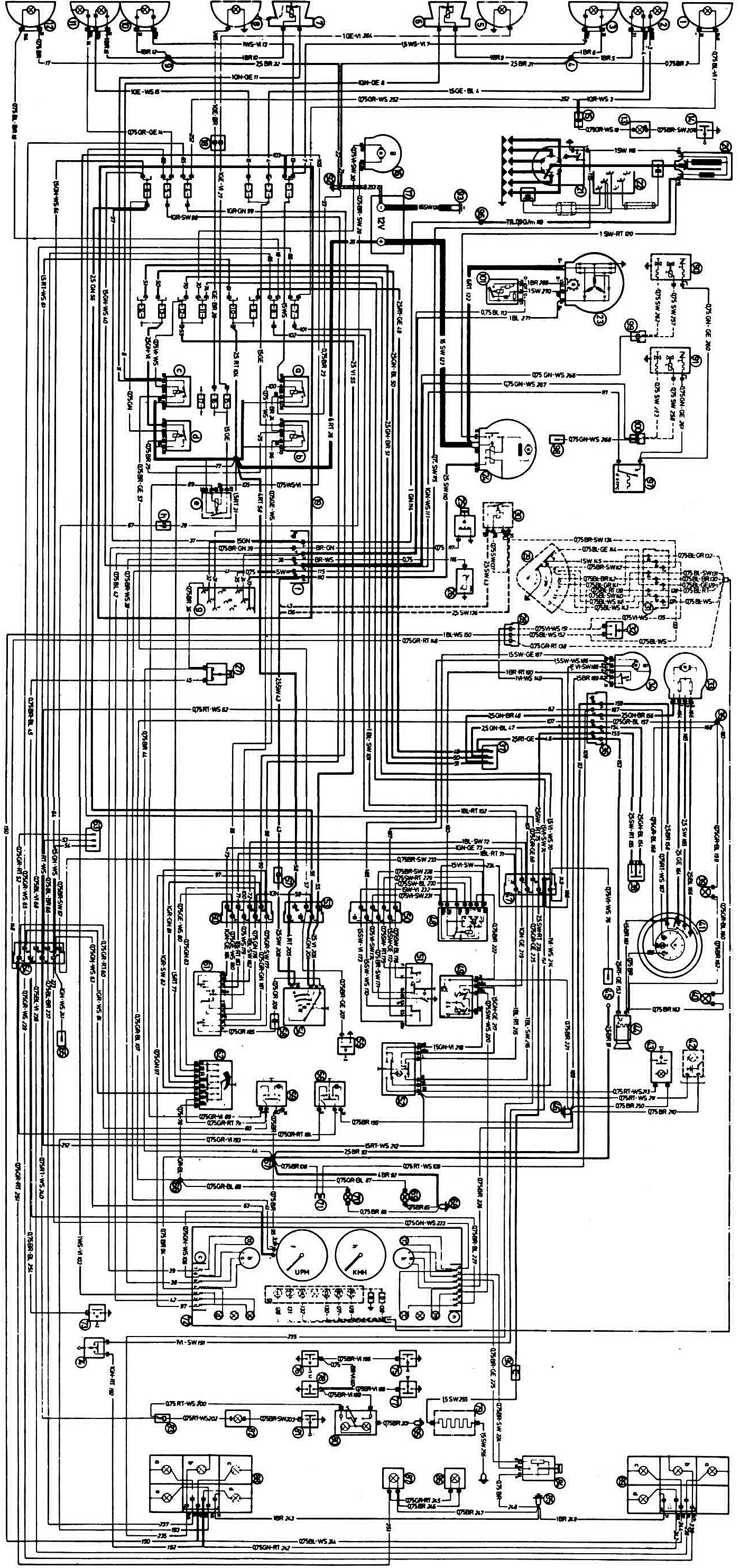
Legend of the electrical equipment diagram
1 - Right front turn signal; 2 - right low beam headlight with side light bulb; 3 - right high beam headlight; 4 — point of connection to the "mass"; 5 - right fog light1); 6 - right sound signal; 7 - left horn; 8 - left fog light1), 9 — point of connection with the "mass"; 10 - Left high beam headlight; 11 — left low beam headlight with side light bulb; 12 - Left front turn signal; 13 — underhood lamp; 14 — underhood lamp switch; 15 — underhood lamp socket; 16 — windshield washer motor; 17 — battery; 18 — fog lamp block; 19 — mounting block: a — high beam headlight relay; b — low beam headlight relay; c — relay for switching on sound signals; d — battery charging circuit relay; e — fog light relay; f — engine connector; g — diagnostic socket; h — terminals for connecting the windshield washer motor; 20 — ignition coil; 21 — ignition distributor; 22 - socket for connecting a tester with a wire and a sensor; 23 - generator; 24 — starter; 25 — oil pressure warning light sensor; 26 — coolant temperature gauge sensor; 27 — brake fluid level indicator lamp switch; 28 — gear shift switch with gear indicator2); 30 — starter relay2); 31 — gearbox switch connector2); 32 - Reverse light switch; 33 — heater fan electric motor; 34 - Windshield wiper motor; 35 - soldering point "58b"; 36 — center console connector; 37 — terminals for connecting electric motors for window lifters, antenna and sunroof; 38 — rear window heating switch; 39,40 — heater control switch illumination lamps; 41 — heater control switch: a — option with clock; b — option with clock backlight; 42 — map lighting lamp1); 43 — glove compartment lighting lamp; 44 — cigarette lighter; 45 - radio receiver; 46 — point of connection with the "mass"; 47 — connector; 48 — Windshield wiper relay; 49 — flasher relay for direction indicators and hazard warning lights; 50 — Windshield wiper switch connector; 51 - Windscreen wiper switch; 52 — hazard warning switch; 53 — ignition switch connector; 54 - ignition switch; 55 - Sound signal switch; 56 — Rear fog light switch; 57 — contact "50" of the anti-theft device; 58 — contact "P" of the ignition switch; 59 - Fog light switch; 60 — connector for turn signal and headlight switch; 61 — direction indicator and headlight switch; 62 - External lighting switch; 63 - three-plug socket; 64 — connector "1"; 65 — terminals for connecting the fuel electric pump; 66 - soldering point "58b"; 67 - soldering point "31"; 68 — point of connection with the "mass"; 69 — lighting lamp "1"; 70 — lighting lamp "2"; 71 — terminal for connecting the clock; 72 — instrument cluster: a — oil pressure warning lamp; b — coolant temperature indicator; c — connector; d — control lamp (blue color) turning on high beam headlights; e — control lamp (red color) battery charge; f — tachometer; g — gear indicator KP2): "P" — white control lamp; "R" — red indicator light; "O" - white control lamp; "A" - green control lamp; "1" - green control lamp; "2" - green control lamp; h — speedometer; i — fuel reserve indicator lamp; k — fuel level indicator; l — brake fluid level indicator light; m — direction indicator lamp; n — connector; o - additional resistance; p — additional resistance; 73 — Parking brake indicator lamp switch; 74 - Brake light switch; 75 — ceiling light switch in the right front door pillar; 76 — ceiling light switch in the left front door pillar; 77 — ceiling light switch in the right rear door pillar; 78 — ceiling light switch in the left rear door pillar; 79 — rear window heating element; 80 — interior light; 81 — Luggage compartment light switch; 82 — luggage compartment light; 82 — luggage compartment light; 83 — trunk lighting connector; 84 — fuel level sensor; 85 — point of connection to the "mass"; 86 - Right license plate light; 87 - left license plate light; 88 — left rear light: a — direction indicator; b — red signal light; c — reverse light lamp; d — brake light bulb; e — rear fog light; 89 - right rear light a - direction indicator, b - red signal light; c — reverse light lamp; d — brake light bulb; 90 - Front carburetor starting device3); 91 - Rear carburetor starting device3); 92 — ground connection point on the body; 93 - ground connection point on the engine; 94 — Rear window heating element connector; 95 — point of connection with the "mass"; 96 — thermal time relay block4); 97 - Thermal time relay4); 98 - starting nozzle4); 99 — Front starter starter connector5); 100 — Rear carburetor starter connector6); 101 - voltage regulator7).
Notes:
- 1) Additional equipment
- 2) For cars with automatic transmission
- 3) Except BMW "520i"
- 4) On the "520i"
- 5) Ground connection point on "520i"
- 6) On the "520i" fuel pump connector
- 7) On BMW "525", "528"
Wire color designation:
- BL — blue;
- BR — brown;
- GE - yellow;
- GR — gray;
- GN - green;
- RT - red;
- SW - black;
- VI - purple;
- WS — white.
The first letters indicate the color of the wire itself, and the second letters indicate the color of the stripe on the wire
(The original article is available on the website: BMWman.ru)