
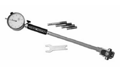
The bore gauge is designed to measure the internal dimensions of parts (for example, the diameter of the cylinder bore, the width of the grooves, etc.).
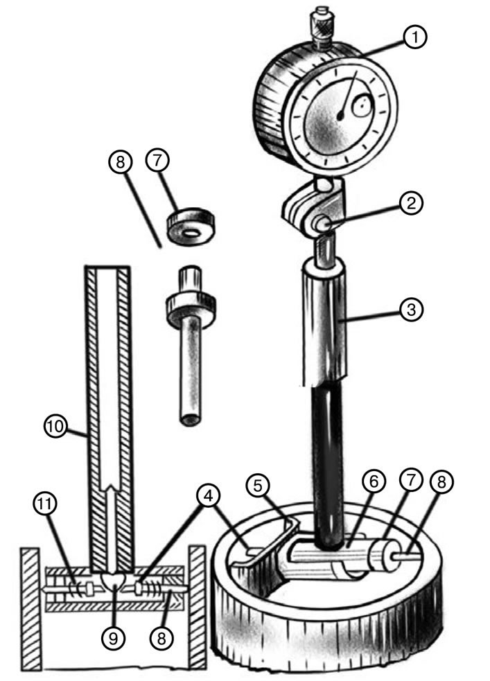
1. Hour type indicator. 2. Screw. 3. Handle. 4. Engine. 5. Centering bridge, 6. Tee. 7. Nut. 8. Measuring rod. 9. Mushroom. 10. Rod. 11. Spiral spring.
The instrument has a guide sleeve (5), in the upper part of which a dial indicator (1) is mounted, secured with a screw (2). Inside the sleeve is a long rod that contacts a short rod (10), which rests against the mushroom (9) of the tee (6) of the bore gauge head. The tee contains a slider (4) and a replaceable measuring rod (8), secured to the tee with a nut (7). A centering bridge 5 is mounted on the tee's sliding pin side, used to adjust the indicator head to the bore diameter. When measuring holes, the engine (4) with the spiral spring (11) presses on the mushroom (9) and through the rod (10) transmits the movement to the long rod to the indicator.
The deviation in size is determined by the movement of the indicator arrow. Before measuring, the bore gauge is set to the nominal size on a ring or block of tiles.
Indicator bore gauges are produced with measurement limits of: 6-10; 10-18; 18-35; 35-50; 50-100; 100- 160; 160-250; 250-450 mm. For measurements, the bore gauge comes with replaceable washers and rods, each with a 1 or 5 mm difference (depending on the measurement limit). The washers are installed into the hole of the head tee.