
- Home
- BMW 3 Series
- E46
- Power unit
- Power system (gasoline)
- Removal, installation and checking the fuel pump relay
Removal, installation and checking the fuel pump relay (BMW 3 Series E46)
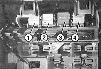
Relay holder
1 - fuel pump relay
2 — heater fan relay
3 - fog light relay
4 - horn relay
The fuel pump relay is located on the relay holder behind the fuse box. It supplies the fuel pump with electrical current. Via a safety switch, it interrupts the fuel supply when no rev pulses are sent when the ignition is on, for example when the engine stalls.
If it is necessary to turn on the fuel pump when the engine is not running to check the injection system, disconnect the relay and connect terminals 30 and 87b with a short auxiliary cable. The wire diameter should be 1.5 mm.
Removal
1. Remove the glove box, refer to Section Removal and installation the left glove compartment and Removal and installation the right glove compartment.
2. Use a small screwdriver to remove the backlight lamp from the side and disconnect the connector.

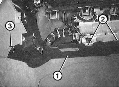
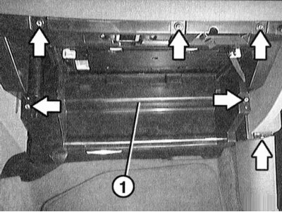
3. Unscrew the screws (arrows in the illustration) and remove cover "1" downwards. From the back of the cover, remove the glove compartment light wire.

4. Press cover "1" back a little and remove it from guides "2". Disconnect the brackets in area "3".

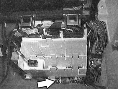
5. Unscrew the screw (arrow on the illustration) and move the relay holder down a little.
6. Remove fuel pump relay "1".
Examination
7. Check the injection system fuse. The location of the fuses is shown in the diagram in the fuse box.
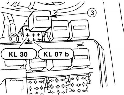
8. Remove relay "3". Connect terminals 30 and 87b with a short auxiliary wire (diesel engine: terminal 87). Be careful not to damage the relay's sensitive contacts. If you can hear the fuel pump turning on, replace the relay.
9. If the pump does not work, check the wires going to the relay and the pump. Replace if necessary.
10. Check relay/fuel pump.
Installation
11. Reinstall the relay.
12. Tilt the relay holder up and secure with the screw.
13. Insert the cover into the guides.
14. Route the wire to the glove box light from the back of the top cover. Secure the cover.
15. Attach the backlight lamp and secure it.
16. Replace the glove box, refer to Sections Removal and installation the left glove compartment and Removal and installation the right glove compartment.
This article is available at russian, bulgarian, belarusian, ukrainian, serbian, croatian, romanian, polish, slovak, hungarian
Article verified: Sevastyanov Nikolay
Share information:
Previous articles
БМВ E46: Power system (gasoline)
Next articles
Similar articles on other types of BMW cars:
Removal and installation, checking of the vacuum pump BMW 5 Series E34 (1988-1996)
Removal and installation / checking the oil pump BMW 5 Series E39 (1995-2003)
Fuel/Fuel Pump Sensor — Removal and Installation BMW 7 Series E32 (1986-1994)
Removal and installation the fuel pump BMW 7 Series E38 (1994-2001)
Removal and installation the fuel filler cap BMW X3 E83 (2003-2010)
Removal and installation the engine BMW X5 E53 (1999-2006)
Link in different formats to this page
Visitor comments
No comments yet
- General information
- Manual
- Maintenance
- Power unit
- Engine repair
- Cooling system
- Power system (gasoline)
- Injection system (gasoline)
- Fuel system (diesel)
- Exhaust system
- Ignition system
- Charge and launch systems
- Transmission
- Car gearbox
- Clutch and drive shafts
- Chassis
- Brake system
- Suspension front and rear
- Steering
- Body
- Body care and repair
- Exterior
- Interior
- Electrical equipment
- Troubleshooting
- Lighting and signaling
- Equipment and devices
- Heater and air conditioner
- Electrical circuits
- General information
- Manual
- Repair on the road
- Weekly checks
- Maintenance
- Troubleshooting
- Power unit
- 4 cylinder engines
- 6 cylinder engines
- Engine overhaul
- Cooling and heating
- Fuel and exhaust system
- Starting and charging system
- Ignition system
- Transmission
- Clutch
- Mechanical gearbox
- Automatic gearbox
- Cardan and drive shafts
- Chassis
- Brake system
- Wheel suspension
- Steering
- Body
- Exterior
- Interior
- Electrical equipment
- Equipment and devices
- Electrical circuits
- General information
- Maintenance
- Power unit
- Engine repair
- Cooling system
- Ignition system
- Supply system
- Fuel injection system
- Exhaust system
- Transmission
- Clutch
- Car gearbox
- Front and rear axle
- Chassis
- Steering
- Brake system
- Body
- Exterior
- Interior
- Electrical equipment
- Heating system
- Equipment and devices
- Power devices
- Electrical circuits
- Power unit
- M10/M20 engine
- M40 engine
- Ignition system
- Lubrication system
- Cooling system
- Supply system
- Fuel injection
- Exhaust system
- Transmission
- Clutch
- Manual gearbox
- Front axle
- Rear axle
- Chassis
- Steering
- Brake system
- Body
- Exterior
- Interior
- Electrical equipment
- Heating system
- Equipment and devices
- Electrical circuits
- General information
- Specifications
- Operation and maintenance
- 4-cylinder engine
- Engine repair
- Cooling and lubrication system
- Supply system
- Ignition system
- 6-cylinder engine
- Engine repair
- Cooling and lubrication system
- Supply system
- Fuel injection system
- Ignition system
- Transmission
- Clutch
- 4-speed manual gearbox
- 5-speed manual gearbox
- Automatic gearbox
- Cardan and rear axle
- Chassis
- Steering
- Front suspension
- Rear suspension
- Brake system
- Electrical equipment
- Equipment and devices
- Electrical circuits