
Replacing the intake camshaft
1. Remove the ignition coils.
2. Remove the spark plugs.
3. Remove the cylinder head cover.
4. Remove the VANOS actuators on the intake and exhaust sides.
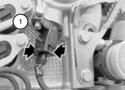
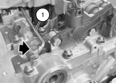
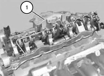
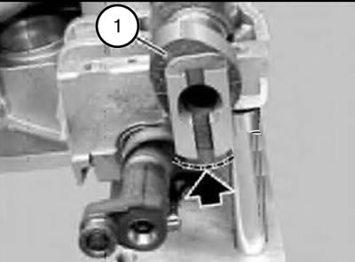
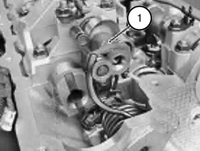
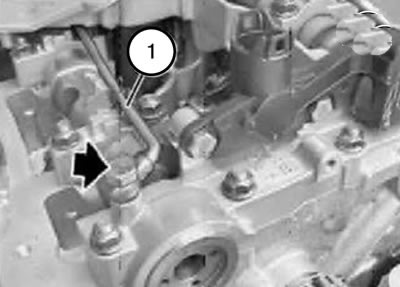
5. Unlock the connector (1) and disconnect it from the intake camshaft pulse sensor.
Note: When installed, the latch on the connector (1) should lock with an audible click.
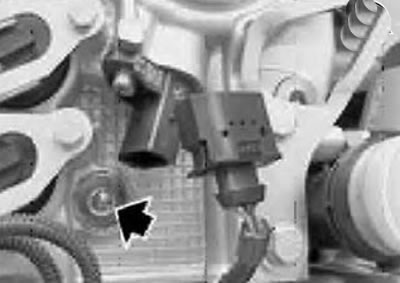
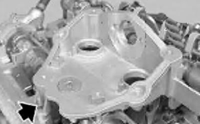
6. Unscrew the screw plug.
Note: The sealing ring must be replaced during installation.
Tightening torque 25 Nm.
Note: Be careful, the bolt may fall out easily.
7. Remove the lower chain guide bar bolt.
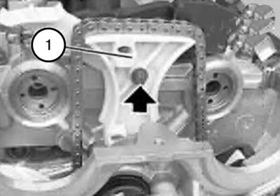
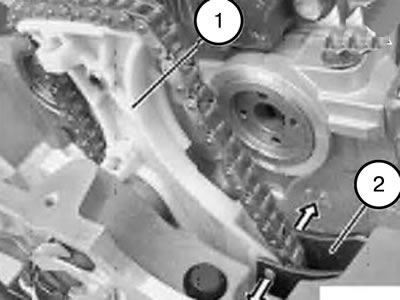
8. Remove the upper bolt of the chain guide bar (1).
Note: The chain guide bars (1 and 2) are secured with 4 protrusions.
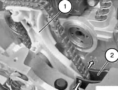
9. Carefully press the chain guide bar (2) and remove the upper chain guide bar (1).
Note: When installing, it is necessary to pull the drive chain up and install the chain guide bar (1).
10. Unscrew the hollow bolt.
11. Move the oil line (1) for lubricating the exhaust camshaft approximately 20 mm downwards.
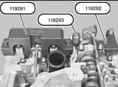
12. Unscrew tool 119293.
13. Remove tools 119291 and 119292.
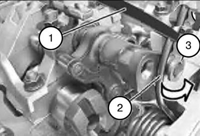
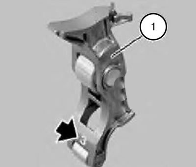
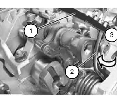
14. Turn the eccentric shaft by the hexagon as shown in the figure to reduce the tension of the torsion spring (2).
15. Create pre-tension of the torsion spring (2) using the bandage (1), remove it from the roller (3) and carefully release the tension.
Attention:
- Risk of injury and possibility of damage.
- The following describes how to remove the support bridge and remove the intake camshaft.
- Strictly follow the order of actions and use of devices.
- Removal the support bridge and removing the intake camshaft without tools is impossible.
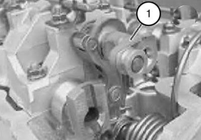
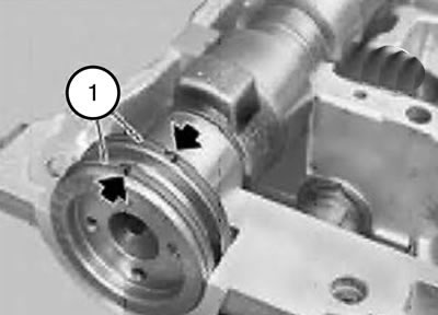
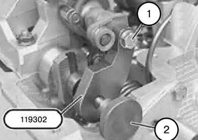
16. Turn the eccentric shaft (1) again by the hexagon, as shown in the figure, to the minimum stroke position.
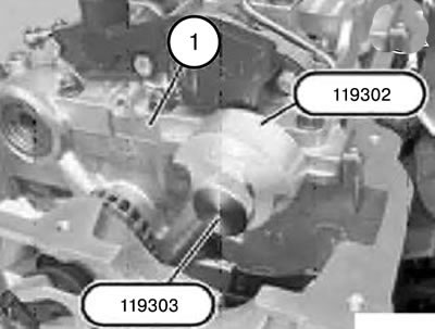
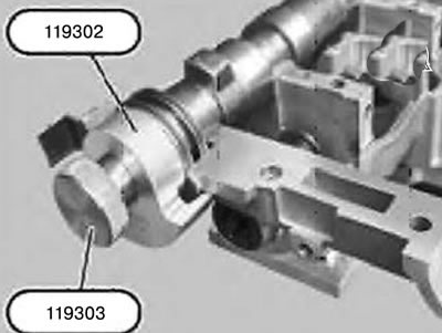
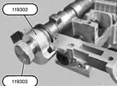
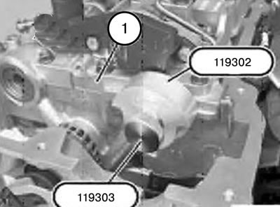
17. Install tool 119302 as shown in the figure and use tool 119303 to screw it onto the intake camshaft.
Note: Tool 119302 secures the intake camshaft to the support bridge (1).
18. Loosen the knurled head screw (2).
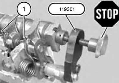
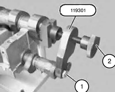
19. Secure tool 119301 with bolt (1) to the eccentric shaft.
20. Align tool 119301 with the intake camshaft.
21. Tighten the knurled head screw (2) until the head fits snugly.
22. Tighten the bolt (1).
23. Lightly tighten the knurled head screw (2) by hand.
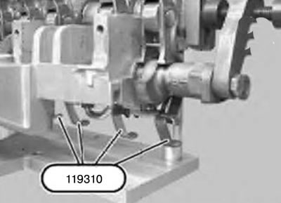
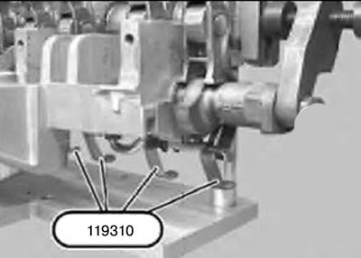
Caution: Before removing the support crossbar, take precautions to prevent the intermediate levers from slipping.
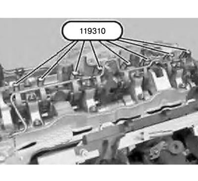
24. Hook the 119310 tool from below into the holes in the intermediate levers and secure it on top of the oil line.
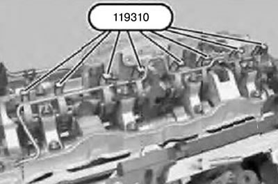
25. Secure all intermediate levers from slipping using tool 119310.
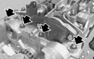
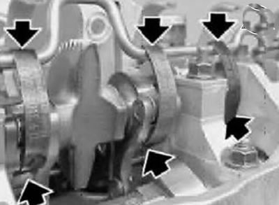
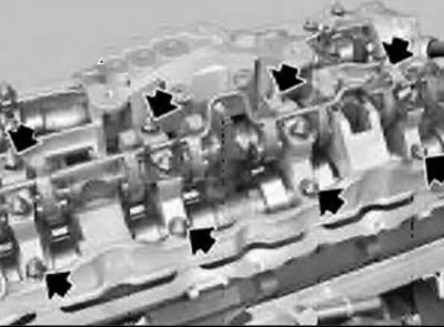
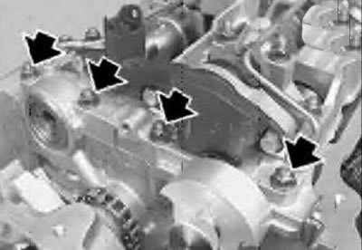
26. Unscrew the 4 nuts on the front support crossbar.
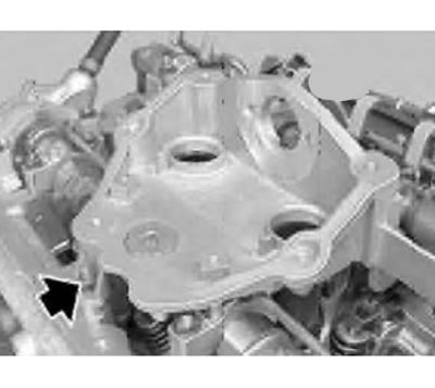
27. Unscrew the nut on the support bridge on the outlet side.
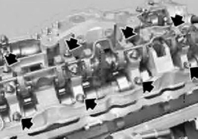
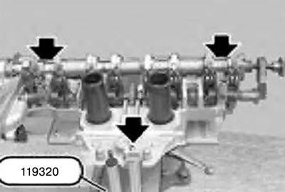
Caution: Only remove the 8 nuts shown in the figure.
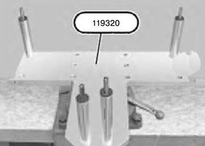
28. Clamp fixture 119320 in a vice as shown in the figure.
Attention:
- Do not turn over the support crossbar (1).
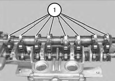
- The levers (1) of the pushers are divided into classes according to tolerances.
- The push rod levers (1) that have been in use can only be reused in the same places.
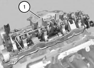
29. Carefully remove the support jumper (1) with an upward movement.
Caution: Do not remove the intake side pushrods.
30. Place the support bridge together with the intake camshaft on top of tool 119320.
Attention:
- Risk of injury and possibility of damage.
- Until the torsion springs (1) are installed, the knurled screw on tool 119301 must not be loosened.
- Only after removing all torsion springs (1) can the intake camshaft be safely removed.
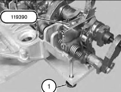
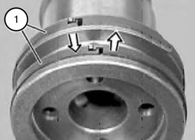
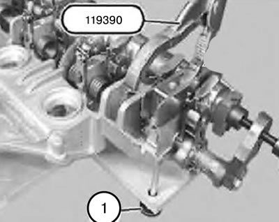
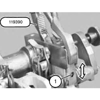
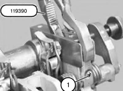
31. Secure tool 119390 with nut (1).
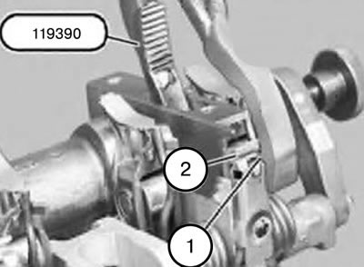
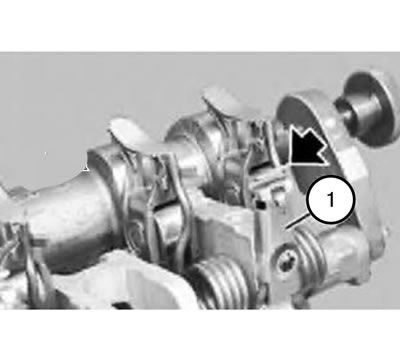
Note: The tab (1) on tool 119390 must engage in the recess (2) on the flange.
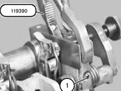
32. Ensure that tool 119390 is secured in the flange as shown in the figure.
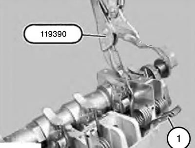
33. Unscrew the screw (1).
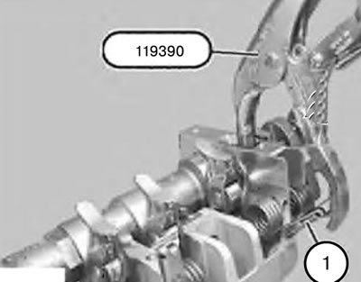
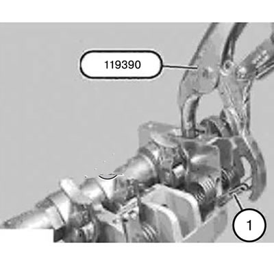
34. Carefully and slowly open the pliers on tool 119390 to remove the pre-tension from the torsion spring (1).
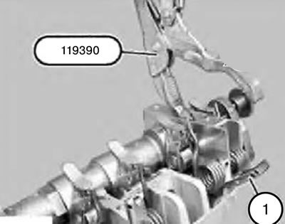
35. Remove the torsion spring (1).
36. Unscrew the nut (1).
37. Remove tool 119390.
38. Remove the torsion springs of cylinders 1 - 3 in the same sequence.
Note: Tool 119310 secures the intermediate lever to the oil line.
39. Remove tool 119310 from the oil line and remove it from the intermediate lever.
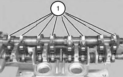
Attention:
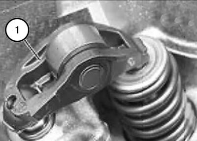
- Intermediate levers (1) are divided into tolerance classes.
- Within one engine, intermediate levers of only one tolerance class can be installed.
- Tolerance classes are designated, as shown in the figure, by numbers from 1 to 6.
- The intermediate levers (1) that have been in use can only be reused in the same places.
40. Remove the intermediate levers (1) and put them aside in strict order.
41. Loosen the knurled head screw (2) on tool 119301.
42. Loosen the bolt (1) and remove tool 119301.
43. Unscrew tool 119303.
44. Remove tool 119302.
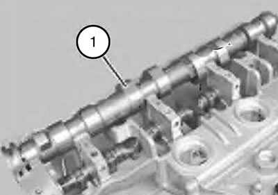
45. Hook and remove the intake camshaft (1).
46. If necessary, replace the rectangular rings (1).
Attention:
- Rings (1) of rectangular cross-section break easily.
- Rectangular rings (1) snap into place at the joint.
47. Press the rectangular ring (1) into the groove on one side, and pull it up on the other side and release the retainer.
48. Carefully spread the ring (1) and remove it forward.
49. Clean all bearing beds and camshaft cams of the intake valves and lubricate with engine oil.
50. Insert rings (1) of rectangular cross-section:
Caution: Rectangular rings (1) are easily broken.
51. Carefully spread the ring (1) and install it in front.
52. Press the rectangular ring (1) into the groove on one side and engage the retainer on the other side.
53. Insert the intake camshaft (1) so that the rounded chamfer points downwards.
54. The ends of the rings (1) of rectangular cross-section point upwards.
55.Make sure that the ends of the rectangular rings (1) snap into place.
56. Install tool 119302 as shown in the figure and use tool 119303 to screw it onto the intake camshaft.
Note: Tool 119302 secures the intake camshaft with a support bridge.

57. Loosen the knurled head screw (2).
58. Secure the device 119301 using the bolt (1) on the eccentric shaft.
59. Align tool 119301 with the intake camshaft.
60. Tighten the knurled head screw (2) until the head fits snugly.
61. Tighten the bolt (1).
62. Lightly tighten the knurled head screw (2) by hand.
63. Lubricate all seating surfaces of the intermediate levers (1) with engine oil and lay the levers down.
Attention:
- Intermediate levers (1) are divided into tolerance classes.
- Within one engine, intermediate levers of only one tolerance class can be installed.
- Tolerance classes are designated, as shown in the figure, by numbers from 1 to 6.
- The intermediate levers (1) that have been in use can only be reused in the same places.
Caution: Before installing the torsion springs, take precautions to prevent the intermediate levers from slipping.
64. Hook the 119310 tool into the holes in the intermediate levers and secure it on top of the oil line.
Note:
- The installation of torsion springs is described using the 4th cylinder as an example.
- For cylinders 1-3, proceed in the same way.
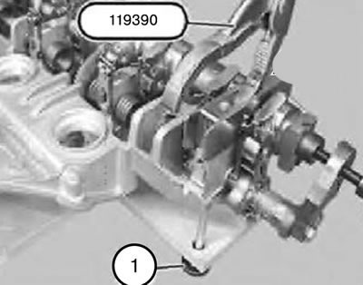
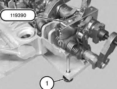
65. Install fixture 119390 on the support crossbar.
Note: Do not tighten the nut (1), just tighten it until it fits snugly.
66. Secure tool 119390 with nut (1).
67. Install the torsion spring (1).
68. Ensure that tool 119390 is secured in the flange as shown in the figure.
69. Carefully and slowly squeeze the pliers on the device 11 90 to create a pre-tension of the torsion spring (1).
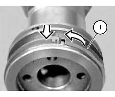
70. Align the hole (1) with the thread using tool 119390.
71. Insert and tighten the bolt (1).
72. Unscrew the nut (1).
73. Remove tool 119390.
74. Install torsion springs of cylinders 1 - 3 in the same sequence.
Note: Minor deformation of the flange (1) when removing and applying tension to the torsion spring is inevitable, but it does not have any effect on operation.
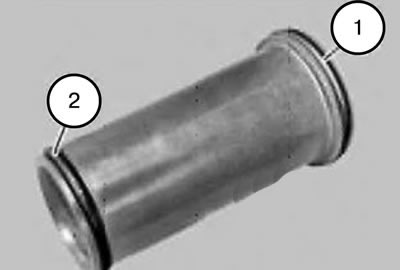
Note: O-rings (1 and 2) are different.
75. Replace the sealing rings (1 and 2) on the high voltage terminals and lubricate with engine oil to facilitate sliding.
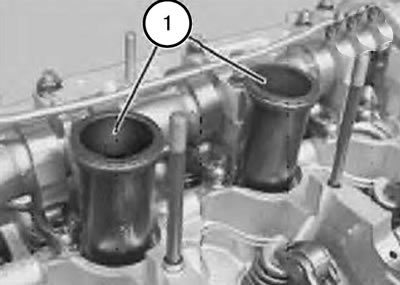
76. Install high voltage terminals (1) of cylinders 2 and 3.
Attention: When installing the reference jumper, it is necessary to align the high voltage terminals (1) with respect to the reference jumper.
Attention:
- The levers (1) of the pushers are easily moved when the support crossbar is installed.
- Make sure that the pushrod levers (1) are secured as shown in the figure to the hydraulic valve clearance compensation system components and to the valves.
77. Align the pusher levers (1) in a straight direction.
Attention:
- Do not turn over the support crossbar (1).
- The pusher rods can be easily moved when the support crossbar is installed.
- Make sure that the pushrods are secured to the hydraulic valve clearance compensation system components and to the valves.
78. Align the push rods in a straight direction.
79. Install the support bridge (1) from top to bottom and carefully bring it into contact with the cylinder head.
80. Screw on eight nuts until they fit snugly.
81. Screw four nuts onto the support crossbar from the front until they fit snugly.
82. Screw the nut onto the support bridge on the outlet side until it fits snugly.
83. Pre-tighten all nuts on the support crossbar from the middle to the edges with a torque of 5 N·m and then finally with a torque of 10 N·m.
84. Remove tool 119310 from the oil line and remove it from the intermediate lever.
85. Loosen the knurled head screw (2) on tool 119301.
86. Loosen the bolt (1) and remove tool 119301.
87. Unscrew tool 119303.
88. Remove tool 119302 from the jumper (1).
89. Turn the eccentric shaft by the hexagon as shown in the figure.
90. Create pre-tension of the torsion spring (2) using the bandage (1) and carefully install it on the roller (3).
91. Turn the eccentric shaft (1) by the hexagon as shown in the figure.
92. Move the oil line (1) for lubricating the exhaust camshaft forward.
93. Insert the hollow bolt and tighten.
94. Pull the drive chain up and install the chain guide bar (1).
Note: The chain guide bars (1 and 2) are secured with 4 protrusions.
95. Carefully press the chain guide bar (2) and install the chain guide bar (1).
96. Assemble the engine.
The original is located on the internet portal: «BMWMAN.ru»