
Removal and installation the cylinder head
1. Remove the air filter housing together with the air flow meter.
2. Remove the ignition coils.
3. Remove all spark plugs.
4. Remove the cylinder head cover.
5. Remove the intake manifold.
6. Remove the exhaust manifold.
7. Remove the exhaust gas shut-off valve.
8. Disconnect the exhaust camshaft position sensor connector.
8. Disconnect the hose from the vacuum pump.
10. Disconnect all cooling system hoses from the cylinder head.
11. Remove the eccentric shaft adjustment motor.
12. Remove the VANOS actuators on the intake and exhaust sides.
13. Remove both solenoid valves.
Attention:
- Replace the cylinder head bolts.
- Do not wash off the coating from the bolts.
- There should be no oil in the blind holes (risk of cracking).
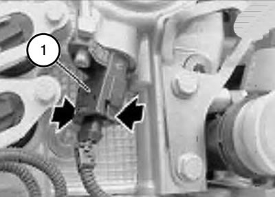
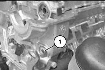
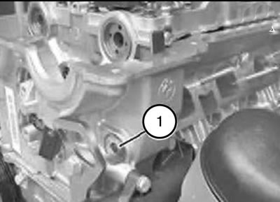
14. Unlock the connector (1) on the camshaft position sensor and disconnect in the direction indicated by the arrow.
Note: When installed, the latch on the connector (1) should lock with an audible click.
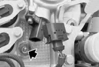
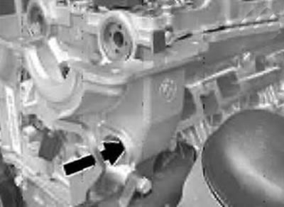
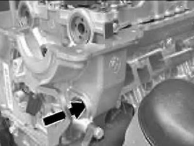
15. Unscrew the screw plug (see arrow).
Note: The sealing ring must be replaced during installation.
Tightening torque 25 Nm.
Caution: Be careful, the bolt can easily fall out.
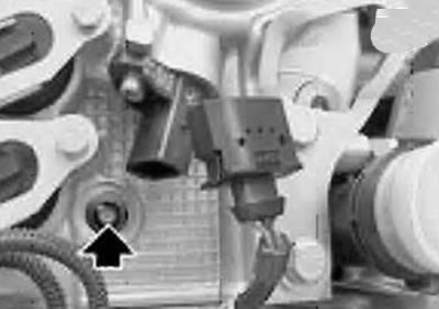
16. Remove the lower chain guide bar bolt.
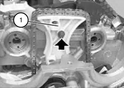
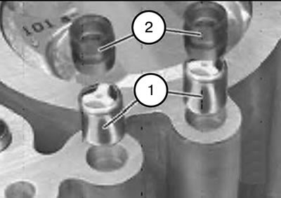
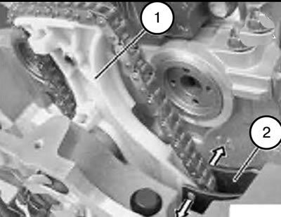
17. Remove the upper bolt of the chain guide bar (1).
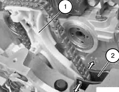
Note: The chain guide bars (1 and 2) are secured with 4 protrusions.
18. Carefully press the chain guide bar (2) and remove the upper chain guide bar (1).
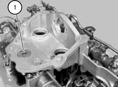
19. Unscrew the threaded plug (1).
20. Remove the chain guide bar hinge pin (see arrow).
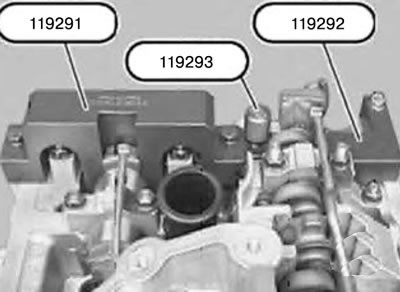
21. Unscrew tool 119293.
22. Remove tools 119291 and 119292.
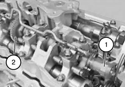
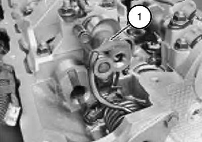
23. Turn the eccentric shaft (1) by the hexagon so that the toothed engagement (2) points towards the inlet, as shown in the figure.
Note: Only in this position are the cylinder head mounting bolts on the intake side accessible.
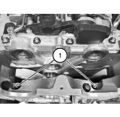
24. Loosen the bolts (1) connecting the cylinder block and the cylinder head.
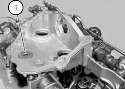
Note: Only after unscrewing the threaded plug (1) does the cylinder head mounting bolt located underneath become accessible.
25. Unscrew the threaded plug (1).
Note:
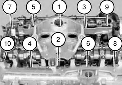
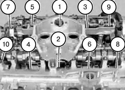
- Bolts (1) - (6) for fastening the cylinder head have M10 threads and an E12 head.
- Bolts (7) - (10) for fastening the cylinder head have MS thread and E10 head.
- The cylinder head mounting bolt (10) is shorter than the others.
- The cylinder head bolt (10) is only accessible via the 1/4-inch E10 end head due to the unfavorable position of the exhaust camshaft.
26. Unscrew the cylinder head mounting bolts from the edges to the middle in sequence 10...1.
27. Remove the cylinder head.
Note: Clean the sealing surface of the cylinder head and block, and if necessary, remove any remaining sealant with a hardwood scraper. When doing this, make sure that no sealant residue gets into the oil and coolant supply channels.
Note:
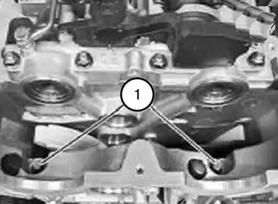
- In the cylinder block on the first cylinder, one check valve (1) and a spacer sleeve (2) are installed on the intake side and the exhaust side.
- In case of severe contamination, it is necessary to replace the check valve (1) and the spacer sleeve (2).
Attention: Pay attention to the direction when installing the check valve (1).
28. Install the check valve (1) and spacer sleeve (2) as shown in the figure.
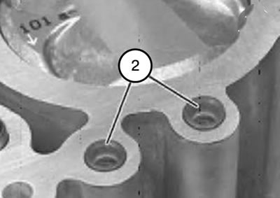
Note: The spacer bushings (2) protrude slightly when installed.
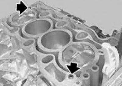
29. Check the centering bushings for damage and correct installation.
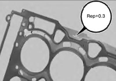
Note: For processed (finishing of flatness) the cylinder heads have a sealing gasket with a repair size 0.3 mm larger.
Attention:
- There should be no oil in the threaded holes of the cylinder block.
- Risk of cracks and incorrect tightening torques.
30. Replace the cylinder head gasket.
31. Install the cylinder head.
32. Replace the cylinder head mounting bolts.
33. Lightly lubricate the mating surface of the washers and the threads of the new cylinder head mounting bolts with oil.
Note:
- Bolts (1) - (6) for fastening the cylinder head have a MU thread and an E12 head.
- Cylinder head mounting bolts (7) - (10) have MB threads and an EYE head. Cylinder head mounting bolt (10) is shorter than the others.
- The cylinder head bolt (10) is only accessible via the 1/4-inch drive cylinder end head due to the unfavorable camshaft position of the exhaust valves.
34. Tighten the cylinder head bolts in sequence 1...10.
Tightening torque: 30 Nm + 90° + 90°.
35. Insert the bolts (1) connecting the cylinder block to the cylinder head and tighten.
36. Replace the sealing ring.
37. Install and tighten the threaded plug (1).
Tightening torque 45 Nm.
38. Align the chain guide bar.
39. Insert the chain guide plate hinge pin and tighten.
40. Replace the sealing ring.
41. Install and tighten the threaded plug (1).
Tightening torque 25 Nm.
42. Turn the eccentric shaft (1) by the hexagon as shown in the figure.
43. Pull the drive chain up and install both solenoid valves
44. Pull the drive chain up and install the chain guide bar (1).
Note: The chain guide bars (1 and 2) are secured with 4 protrusions.
45. Carefully press the chain guide bar (2) and install the chain guide bar (1).
46. Install the intake and exhaust VANOS actuators.
47. Replace the drain plug sealing ring.
Tightening torque of the drain plug: 25 Nm.
48. Bleed the cooling system and check it for leaks.
49. Assemble the engine.