
2. Remove the ignition coils.
3. Remove all spark plugs.
4. Remove the cylinder head cover.
5. Remove the eccentric shaft adjustment motor.
6. Remove the generator drive belt.
7. Remove the torsional vibration damper.
8. Remove both solenoid valves.
9. Fix the engine in the mounting position.
10. Lower the front suspension crossmember.
11. Remove the oil pan.
12. After removing the oil pan, temporarily install the front axle beam in its original place and remove the device for fixing the engine in the mounting position.
Attention:
- To remove the drive chain, you need to loosen the central bolt and then remove it.
- After loosening the center bolt, the drive chain sprocket and oil pump sprocket are no longer connected to the crankshaft (danger of damage).
- The balance shafts rotate and must be readjusted as described below.
13. Turn the engine crankshaft by the central bolt in the direction of rotation until the piston of the 1st cylinder is at TDC at the end of the compression stroke.
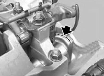
Note:
- The flat for fixing the intake camshaft is rounded on the upper side and straight on the lower side.
- When the piston of the 1st cylinder is at TDC at the end of the compression stroke, the chamfer with a rounding points upwards in the direction of the cylinder axis.
Note:
- The chamfer for fixing the exhaust camshaft is rounded on the upper side and straight on the lower side.
- When the piston of the 1st cylinder is at TDC at the end of the compression stroke, the chamfer with a rounding points upwards in the direction of the cylinder axis.
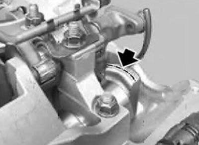
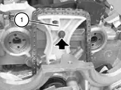
Additional differences in the exhaust camshaft:
- When the piston of the 1st cylinder is in the TDC position at the end of the compression stroke, the grooves (1) in the exhaust camshaft point towards the exhaust manifold.
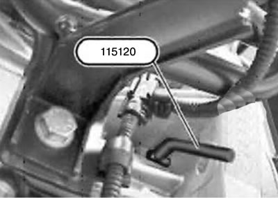
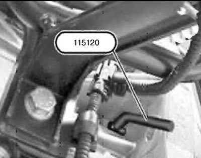
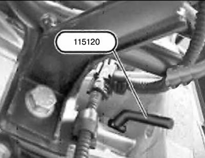
14. Turn the engine crankshaft by the central bolt and fix the flywheel using tool 115120 with the piston of the 1st cylinder at the TDC end of the compression stroke.
Note:
- Only for models with automatic transmission.
- The picture shows without automatic transmission.
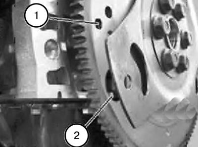
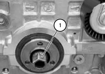
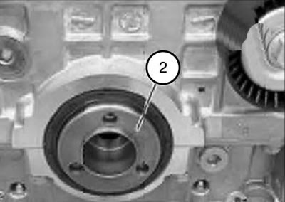
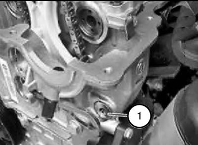
Attention:
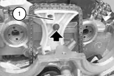
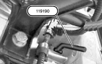
- On engines with automatic transmission, next to the hole (1) for fixing in the TDC position, there is a large hole (2), which can be confused with the hole for fixing.
- If the flywheel is locked in the correct hole (1) using tool 119190, the engine will no longer turn on the central bolt.
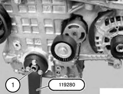
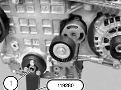
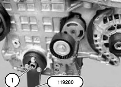
15. Install tool 119280 onto the vibration damper hub.
Caution: If the center bolt is tightened to the specified torque, do not use torque wrench 115120 to loosen the center bolt.
16. Pull tool 115120 back just enough to release the flywheel.
Caution: Do not allow the engine to crank.
Note: When loosening and tightening the central bolt (1), have a second person hold it using tool 119280.
17. Loosen the central bolt (1) by about a quarter of a turn.
18. Remove tool 119280.
19. Turn the engine crankshaft by the central bolt and fix the flywheel using tool 115120 with the piston of the 1st cylinder at the TDC end of the compression stroke.
Note:
- Do not turn the engine if the center bolt is loose.
- The engine is locked with device 119190/115120.
20. Remove the VANOS system actuators on the intake and exhaust sides,
Note:
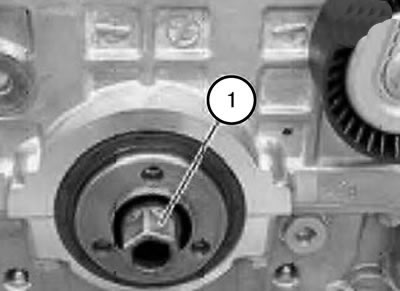
- The central bolt (1) is still tightened to a torque of approx. 60N-M.
- To further loosen the bolt, use tool 119190/115120.
21. Unscrew the loosened central bolt (1).
22. Remove the hub (2) forward.
Note: Replace the oil seal when installing.
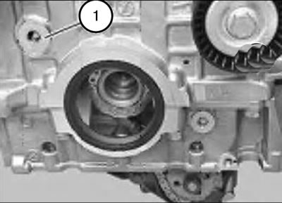
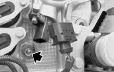
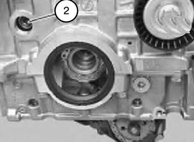
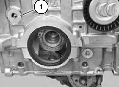
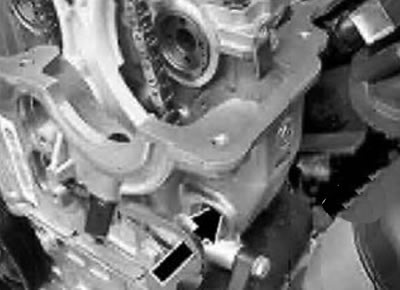
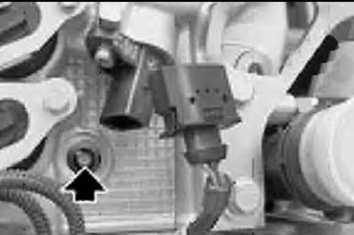
23. Unscrew the threaded plug (1).
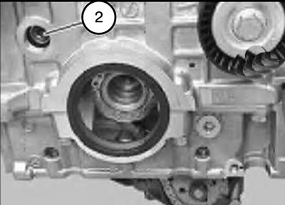
24. Unscrew the pin (2) of the chain tensioner bar hinge.
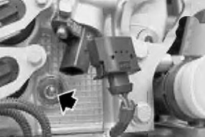
25. Unlock and disconnect the connector of the intake camshaft pulse sensor.
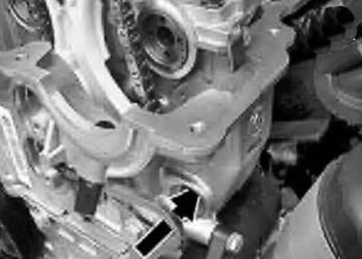
26. Unscrew the screw plug.
27. Remove the lower chain guide bar bolt.
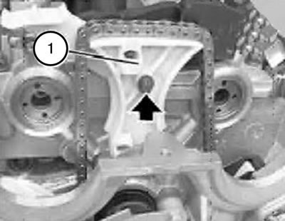
28. Remove the upper bolt of the chain guide bar (1).
29. Unscrew the screw plug.
30. Remove the chain guide bar hinge pin.
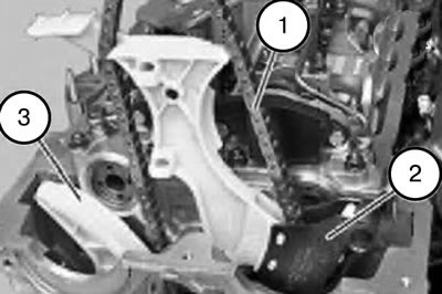
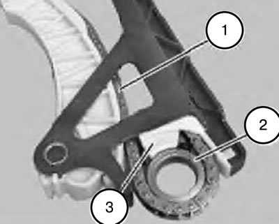
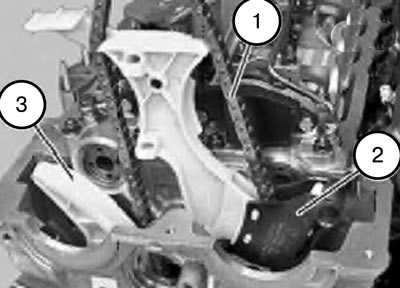
31. Remove the chain guide bar with the drive chain (1), the chain guide bar (2) and the tensioner bar (3) as an assembly by moving it upwards.
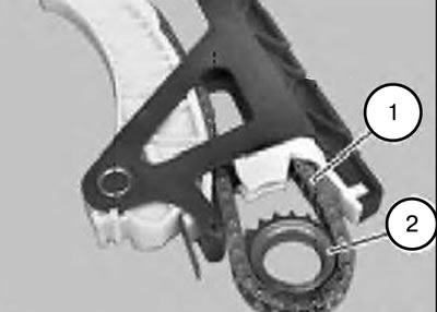
32. Pull the drive chain (1) downwards and remove the sprocket (2).
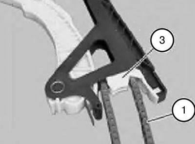
33. Carefully press the chain guide bar (3) and remove the drive chain (1).
34. Check the chain guide bar and replace if necessary.
35. Carefully press the chain guide bar (3) and thread the drive chain (1).
36. Pull the drive chain (1) upwards.
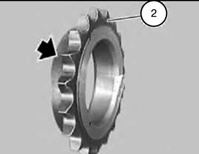
Attention:
- Pay attention to the direction when installing the sprocket (2).
- The flange on the sprocket (2) points towards the crankshaft.
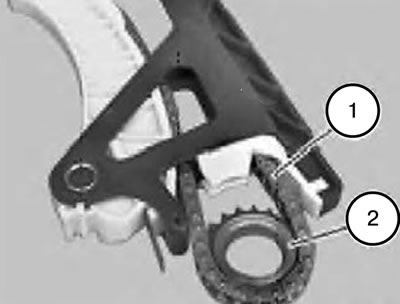
37. Place the drive chain (1) on the sprocket (2).
38. Pull the drive chain (1) upward until the sprocket (2) touches the chain guide bar (3).
39. Hold the drive chain (1) and sprocket (2) in this position.
40. Install the chain guide bar with the drive chain (1), the chain guide bar (2) and the tensioner bar (3) in assembly, moving from top to bottom.
41. Insert the pin (2) of the tensioner bar hinge and tighten.
42. Replace the sealing ring of the threaded plug (1).
43. Install and tighten the threaded plug (1).
Tightening torque 45 Nm.
44. Insert the chain guide plate hinge pin and tighten.
45. Replace the sealing ring of the threaded plug (1).
46. Install and tighten the threaded plug (1).
Tightening torque 25 Nm.
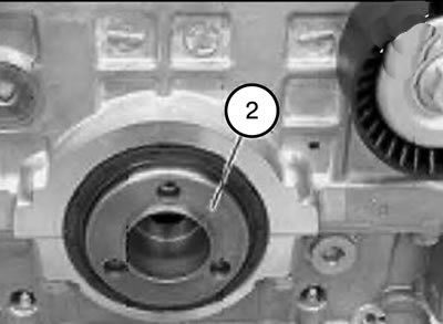
47. Check the hub (2), replace if necessary.
48. Install the hub (2).
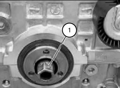
Note: When installing, it is necessary to replace the central bolt (1).
49. Insert the central bolt (1) and tighten until it fits snugly.
Caution: Do not tighten the central bolt (1) yet.
Note:
- Old version
- With the central bolt loosened, the balance shafts can be rotated by hand at the ends.
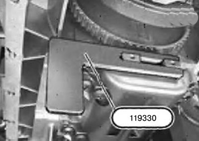
50. Align the balance shafts so that tool 119330 can be placed from the intake side onto the ends of the balance shafts.
Note:
- New performance.
- With the central bolt loosened, the balance shafts can be rotated by hand at the ends.
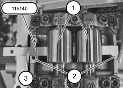
51. Align the balance shafts so that tool 115140 can be fitted on the intake side below the balance shafts.
Attention:
- The engine is locked with tool 119190/115140 inserted into the locking hole.
- To tighten the central bolt (1) to 60 Nm, use the anti-rotation tool 119190/115140.
- At a torque exceeding 60 Nm, damage to the 119190/115140 device and the cylinder block occurs.
52. Pre-tighten the central bolt (1) to 60 Nm.
53. Install both solenoid valves
54. Insert the upper bolt of the chain guide bar (1) and tighten until the head fits snugly.
55. Insert the lower chain guide plate bolt and tighten.
56. Tighten the upper bolt of the chain guide bar (1).
57. Replace the sealing ring of the threaded plug.
58. Insert the threaded plug and tighten.
Tightening torque 25 Nm.
59. Disconnect the connector from the intake camshaft pulse sensor.
Note: The latch on the connector should lock into place with an audible click.
60. Install the intake and exhaust VANOS actuators.
61. Install the eccentric shaft adjustment motor.
62. Install the cylinder head cover.
63. Screw in all spark plugs.
64. Install the ignition coils.
65. Replace the front crankshaft oil seal.
66. Remove tool 119190/115120.
67. Install tool 119280 onto the vibration damper hub.
68. Tighten the central bolt (1).
Tightening torque: 300 Nm.
69. Fix the engine in the mounting position.
70. Lower the front axle beam again.
71. Install the oil pan.
72. Install the front axle beam.
73. Install the torsional vibration damper.
74. Install the generator drive belt.
75. Assemble the engine.