
Replacing the bearings of the secondary and intermediate shafts
Heat the gearbox housing on a hot plate to about 80°C and press the bearings out of their sockets.
New bearings are pressed in with the inscriptions towards the rear of the gearbox.
Assembly
During the assembly process of the gearbox, it is necessary to lubricate the parts with gearbox oil as they are installed.
Clamp the output shaft in a vice with pads made of soft material.
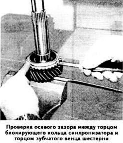
Install the needle bearing, 2nd gear gear and synchronizer blocking ring on the corbel of the secondary shaft. Measure the gap between the end face of the blocking ring and the end face of the ring gear. If it is less than 0.8 mm, replace the synchronizer ring.
Install the 1st and 2nd gear synchronizer sleeve hub and the second synchronizer blocking ring onto the output shaft.
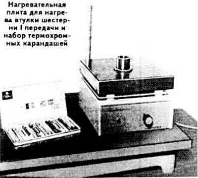
Heat the 1st gear bushing on the heating plate to a temperature of 100-120°C; at the same time, it is recommended to control the temperature with thermochromic pencils (e.g. manufactured by Faber Castell).
Press the needle bearing, 1st gear gear and bushing onto the secondary shaft (first make sure that it is heated to the set temperature) with a mandrel and a hammer.
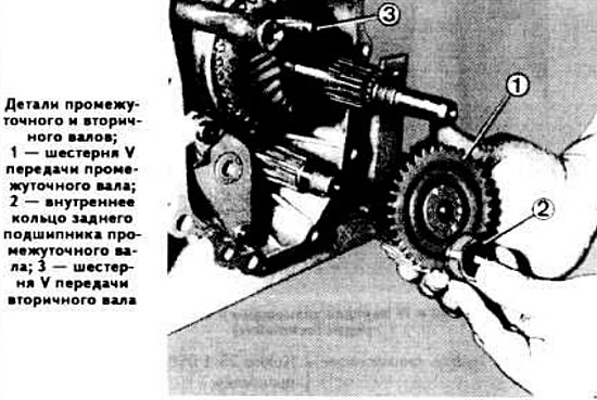
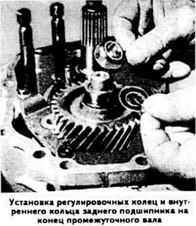
Install a 0.10 mm thick adjusting ring on the output shaft, and then put the inner race of the roller bearing installed in the intermediate case onto the shaft, using a mandrel if necessary.
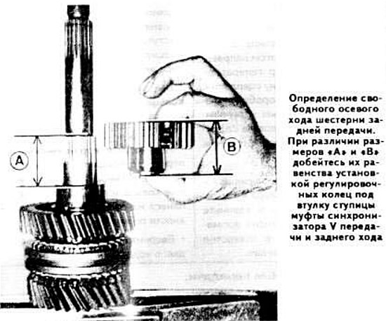
Determine the axial free play of the reverse gear, which is correct if the distance «A» (see photo) between the end face of the bearing race and the shoulder of the secondary shaft is equal to the height «IN» the hub of the synchronizer coupling of the V gear and reverse gear, complete with the bushing. If necessary, achieve equality in size by installing adjusting rings under the sleeve of the hub of the synchronizer coupling of the V gear and reverse gear.
Take out a secondary shaft from a vise, turn over and clamp in a vice again.
Install the needle bearing on the secondary shaft (with plastic separator) 3rd gear gear, 3rd gear, synchronizer blocking ring, 3rd and 4th gear synchronizer sliding clutch hub, pointing the shoulder towards the 4th gear, adjusting ring and retaining ring. By selecting the thickness of the adjusting ring, ensure a tight fit of the parts.
Install the blocking ring of the synchronizer of III and IV gears on the secondary shaft and press the bearing onto the end of the shaft.
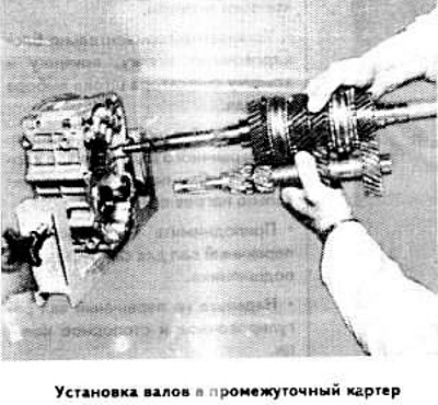
Connect the input shaft to the output shaft.
Position the intermediate shaft against the input and output shaft assemblies and insert the shafts into the intermediate housing.
Place the gearbox in a vertical position with the gear clusters down, holding the shafts with a tube resting against a wooden lining.
Heat the reverse gear bushing to 100-120°C.
Install adjusting rings of the required thickness (see above), then press on the bushing of the reverse gear using drift 23 1 160.
Install needle bearing (with plastic separator) and reverse gear.
Place the gearbox in a horizontal position.
Connect the hub and the sliding clutch of the synchronizer of the 5th gear and reverse.
Insert the ball of the retainer of the 5th gear and reverse fork rod into the socket of the intermediate housing.
Connect the rod with the 5th gear and reverse fork assembly with the hub and synchronizer clutch and install them in the gearbox housing.
While holding the rod, replace the pin of the V gear and reverse gear fork, move the rod, the plug with the hub and the V gear and reverse gear synchronizer clutch, and then shift the synchronizer clutch hub to the stop.
Bring the rods together with the shift forks of III and IV, I and II gears to each other.
Install the ball of the retainer of the rods of the forks for engaging the 5th gear and reverse gear and shifting the III and IV gears into the socket of the intermediate crankcase, then put the ball of the retainer of the rod of the shift fork of the III and IV gears in place.
Install the 1st and 2nd, 3rd and 4th gear shift fork rod retainer ball into the intermediate crankcase socket, then replace the 1st and 2nd gear shift fork rod retainer hinge and install this rod. If necessary, remove the cover from the 1st and 2nd gear fork rod retainer socket. After installing the stem, be sure to replace the retainer cover.
Establish a rod of a choice of transfers in gathering with a leash and intermediate draft.
Install the intermediate lever with the rounded part down and screw the axle bolt into the intermediate housing, having previously applied a special adhesive such as Loctite to the threads.
Install the tie rod support by tightening the mounting screw.
Fix the gear selection lever and the shift fork of III and IV gears with pins.
Place the gearbox in a vertical position with the gear clusters down.
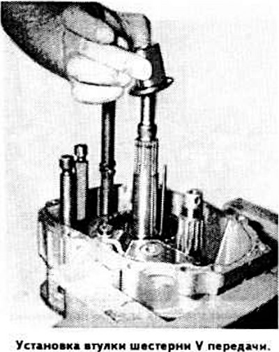
Heat, if necessary, the bushing of the gear wheel of the 5th gear to a temperature of 100-120°C.
Install jig 23 1 450 on one of the guides of the 5th gear and reverse synchronizer clutch hub and press the 5th gear bushing onto the secondary shaft using drift 23 1 040 and a hammer, then remove the jig.
Establish a blocking ring of the synchronizer of V transfer and a backing.
Press the V gear and needle bearing onto the secondary shaft.
Press the 5th gear onto the intermediate shaft using drift 23 1 040.
Press the 5th gear bushing onto the intermediate shaft, preheating it.
Install the shims on the 5th gear bushing and press the inner race of the bearing onto the end of the intermediate shaft.
Insert a pin into the hole at the end of the intermediate shaft. Check if the parts are tight at the end of the intermediate shaft. If this is not the case, replace the adjusting rings with thicker rings.
Install the spacer ring on the V gear of the output shaft and press the speedometer drive gear onto the shaft, preheating it.
Press on the rear end of the intermediate shaft bearing with a large cage diameter away from the 5th gear.
Put the gearbox and horizontal position.
Move the 1st and 2nd gear fork rod to the position corresponding to the 2nd gear engagement; at the same time, lift the leash in a position in which the orientation of the end of the rod would ensure the installation of the blocking cracker of the rods of the shift forks of 1st and 2nd gears and the inclusion of 5th gear and reverse gear.
Establish a cover of the back bearing of a secondary shaft (without putting a gasket), by applying a sealant such as Loctite 573 to the mating surfaces.
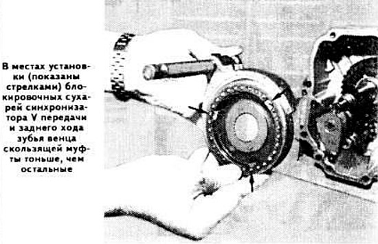
Insert the 1st and 2nd gear shift fork rod into the rear cover of the gearbox. Remove the inspection hole cover and make sure that the blocking block is in the correct position, then replace the cover.
Wrap the left top bolt of fastening of a back cover to an intermediate crankcase.
Install the pin in the hole of the shift fork of 1st and 2nd gears.
Insert the two dowel pins of the rear cover into the holes in the intermediate case.
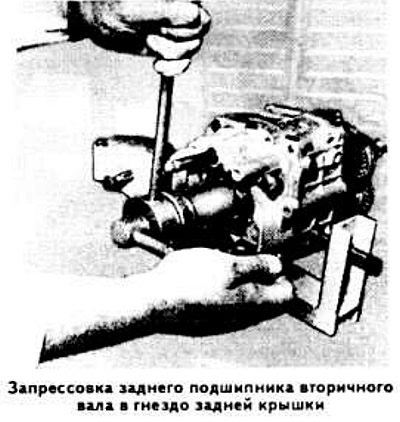
Heat the rear cover and press the output shaft rear bearing into its seat with the lettering from its cover using shim 7026-1 amendment 7026; at the same time, for a secure fit of the bearing, hit the mandrel several times with a hammer.
Turn the gearbox over with the output shaft up.
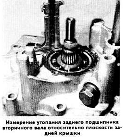
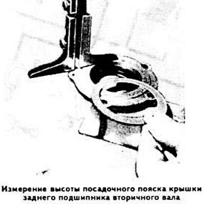
Install the gasket of the rear bearing cover of the output shaft and measure with a depth gauge the sinking of the bearing relative to the plane of the rear cover, and then the height of the seating belt of the bearing cover. The difference in the measurement results determines the thickness of the adjusting ring to be installed.
Install an adjusting ring on the rear bearing of the secondary shaft, ensuring that there is practically no gap between the bearing and the cover (preload must not exceed 10/100).
Establish a cover of the back bearing of a secondary shaft, having tightened bolts of fastening; while the short bolt must be inserted into the upper right hole of the cover.
Press the flange onto the splines of the secondary shaft using the 7026 mandrel and thrust spacer (as the latter, you can use the old thrust sleeve.)
Tighten the output shaft flange nut by installing a protective sleeve on its end. When performing this operation, use retainer 6039 and a 30 mm sleeve.
Press the front bearing of the intermediate shaft into the seat of the gearbox housing, having previously laid grease in the bearing; while directing the larger diameter generator» bearing towards the clutch. Connect the gearbox housing to the intermediate housing, having previously applied sealant such as Loctite 573 to the mating surfaces.
Screw the bolts securing the intermediate housing to the gearbox housing and push the two locating pins of the intermediate housing into the hole in the transmission housing.
Tighten the bolts securing the intermediate housing to the gearbox housing.
Install the lockout sleeve, spring and selector rod retainer cover horizontally.
Press the front bearing of the input shaft into the seat of the gearbox housing, preheating it.
Raise the input shaft several times to self-align the bearing.
Put on a primary shaft an adjusting and lock ring.
Measure the distance between the input shaft front bearing end and the bearing surface of the front cover. Compare the measurement with the protrusion of the outer race of the bearing when it is installed in the front cover.
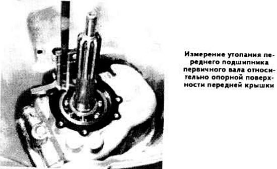
Choose shims that are thick enough to ensure a snug fit.
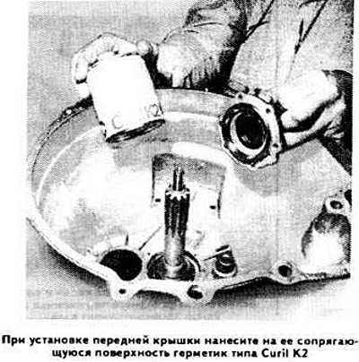
Press on the input shaft front bearing outer race, install the shims and front cover, applying Curil K2 type sealant to the mating surfaces.
Screw in the reverse light switch.