
Removal a manual transmission (GS 6 - 37 BZ) assembled
Attention: After completing the work, check the oil level.
Attention:
- Use only certified brands of transmission oil.
- Failure to comply with this rule will result in serious damage to the manual transmission.
1. Disconnect the battery.
2. Remove the front panel of the engine auxiliary mechanisms protection.
3. Remove the exhaust system assembly.
4. Remove the heat-insulating screen.
5. Disconnect the front propeller shaft from the transfer case and lift it off the ground.
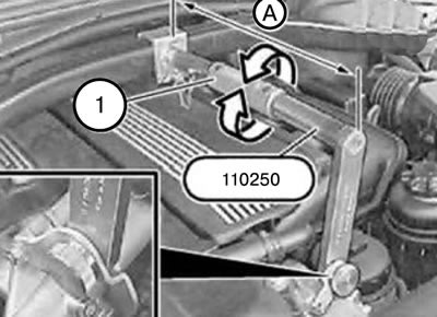
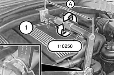
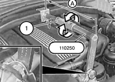
6. Install tool 110250 between the tensioner and the engine eye and secure it with a pin.
7. Using the coupling (1), create tension on the device by adjusting dimension A.
Size A: 36 cm.
8. Fix the engine in the mounting position.
9. Disconnect the propeller shaft from the gearbox.
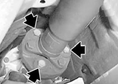
10. Unscrew the intermediate support.
11. Move the cardan shaft to the side and tie it up.
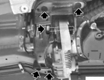
12. Loosen the mounting screws and remove the gearbox mounting cross beam.
Tightening torque:
- Gearbox mounting beam to body mounting screws: 21 Nm.
- Gearbox mounting beam to rubber mount mounting screws: 73 Nm.
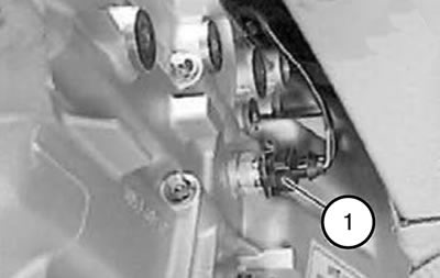
13. Disconnect the connector (1) from the reversing light switch.
14. Remove the cables from the holders, move them to the side and tie them up.
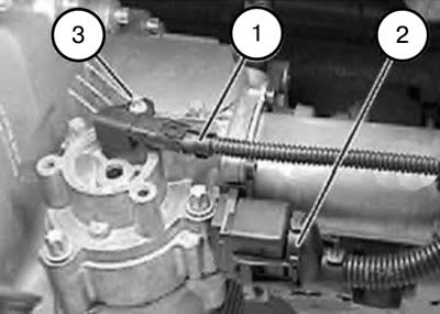
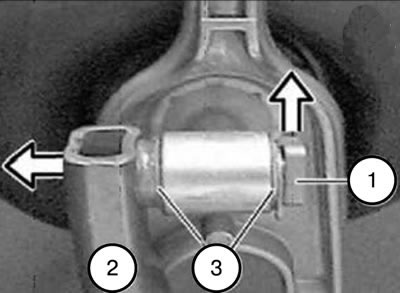
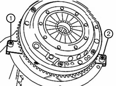
15. Disconnect connectors (1) and (2) from the servomotor.
Note: Do not disconnect the pressure line of the clutch slave cylinder.
Caution: The vacuum in the clutch slave cylinder must be reduced gradually to prevent air from being sucked into the cylinder through the sealing cuff.
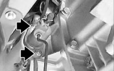
16. Loosen the nuts and remove the slave cylinder.
Tightening torque: 22 Nm.
17. Using the coupling (1), set the tool 110250 back to dimension "A".
Size "A": 34 cm.
18. Bring the gearbox into the dismantling position.
Caution: When lowering the gearbox, ensure that the engine does not rest on the front shield.
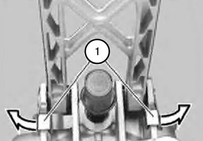
19. Unlock the hinge pin (1) in the direction indicated by the arrow and remove it.
20. Remove the gear shift lever support rod by moving it upwards.
Note: When installing, it is necessary to lubricate the pin (1) with KlberPofyiub GLY801 grease.
21. Remove the retainer (1).
22. Disconnect the gear shift drive rod (2).
Note:
- When installing, it is necessary to lubricate the gear shift drive rod with Klber Poiylub GLY801 grease.
- Pay attention to the correct position of the spacer washers (3).
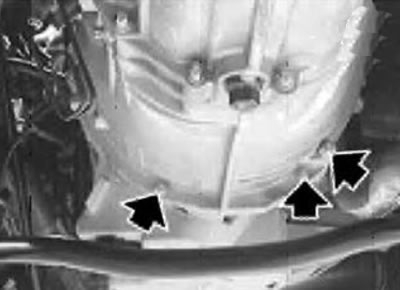
23. Remove the screws.
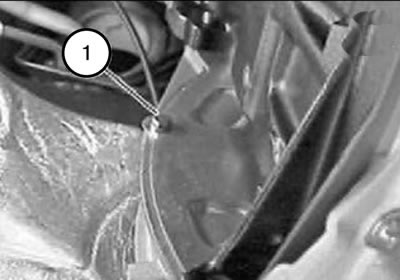
24. Unscrew the screw (1).
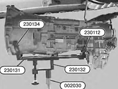
25. Support the gearbox using tools 230134, 230131, 230132, 230112 and 002030.
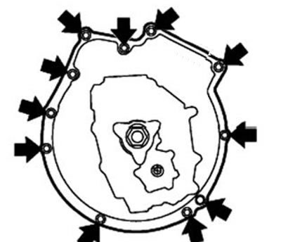
26. Remove the screws.
Caution: When removing and installing the gearbox, do not let it hang on the input shaft; otherwise, the clutch disc may become deformed. Move the gearbox back and remove it.
Note:
- When installing, it is necessary to check the correct position of the centering bushings.
- Replace damaged centering bushings.
- Make sure the covers are installed correctly.
Note:
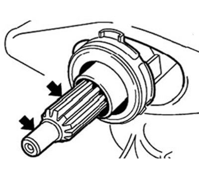
- When installing, it is necessary to check whether the grease on the input shaft of the gearbox is sticky. If the grease is sticky, clean the input shaft and replace the clutch disc.
- Check the driven clutch disc for rust in the splines and replace if necessary.
- Use a rag to remove old grease and dust formed during wear of the friction lining from the splines of the driven clutch disc.
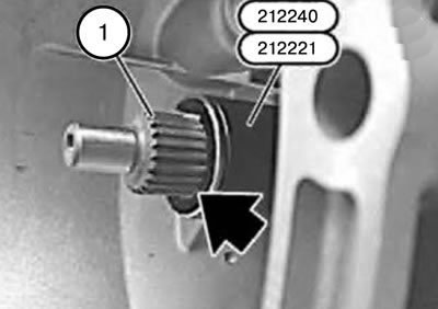
Note:
- When installing, it is necessary to remove and clean the release bearings and the clutch release fork.
- Fit oil scraper ring 212221 all the way.
- Lubricate the splines (1) of the input shaft with a brush.
- Remove the oil scraper ring.
Note: Before installing the gearbox mounting cross member using the coupling (1), reinstall tool 110250 to dimension "A" (mounting position).
Size "A": 36 cm.
27. Installation should be carried out in the reverse order of removal, taking into account the above notes.
[The website served as the basis for the text «BMWman.ru»]