
- Home
- BMW 3 Series
- E46
- Power unit
- Fuel and exhaust system
- Emission Control Systems — Replacement of Components
Emission Control Systems — Replacement of Components (BMW 3 Series E46)
Crankcase ventilation control
1. The units of this system do not require special attention, except for periodic checking of the condition of the hoses.
Replacing the carbon filter
2. The carbon filter is located at the rear under the vehicle. To access the filter, lift the rear of the vehicle and place it on stands.
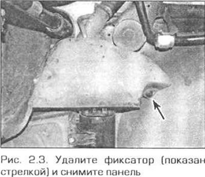
3. Remove the screws, remove the retainer and remove the plastic panel (if there is one) on the right side of the spare wheel well (Fig. 2.3).
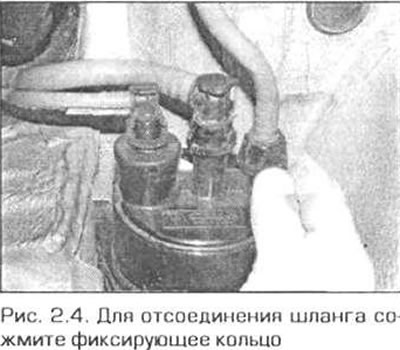
4. Disconnect the hoses from the carbon filter. If the hoses have plastic connections, squeeze the retainer ring and pull the hose off. Mark the hoses to avoid mixing them up during assembly (Fig. 2.4).
5. Loosen the screws and remove the carbon filter with the bracket.
6. Installation is carried out in the reverse order. Be careful not to mix up the hoses. Check that the hoses are securely fastened.
Replacing the purge valve
Engine M43TU
7. The valve is located on the bracket next to the air cleaner.
8. Turn off the ignition.
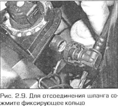
9. Disconnect the hose from the carbon filter (Fig. 2.9).
10. Disconnect the electrical connector plug from the valve.
11. Turn the valve 90° counterclockwise and pull it upward at the same time to disconnect the remaining hoses.
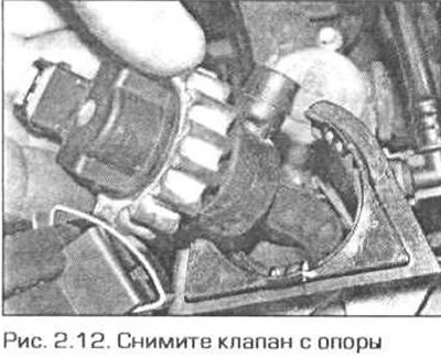
12. Remove the valve from the support (Fig. 2.12).
13. Install the valve in the reverse order of removal. Be careful not to mix up the hoses.
Engine N42
14. The valve is located under the intake manifold. For better access, remove the air duct for the ventilation and heating system in the rear of the engine compartment as follows.
- a) Remove the cabin filter cover by turning its latches 90' counterclockwise. Pull the filter out of the housing.
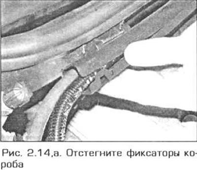
- b) Unfasten the 4 fasteners of the box for laying the wires and remove the sleeves with wires from the box (fig. 9.14,a).
- c) Remove the four screws and pull the cabin filter housing forward.
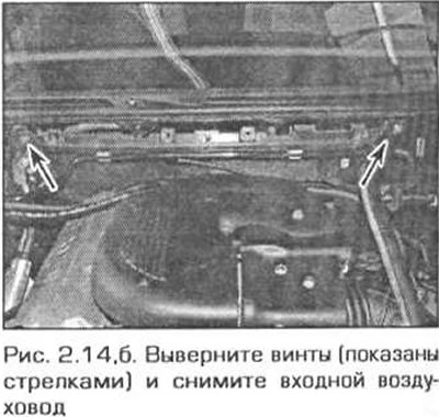
- d) Unscrew the two screws and remove the air duct (fig. 2.14.b).
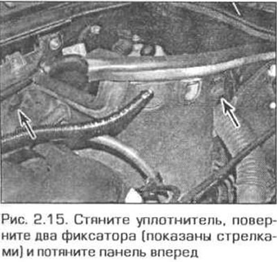
15. In the left rear corner of the engine compartment, pull off the seal, turn the two fasteners counterclockwise and remove the trim panel (Fig. 2.15). Pull the hoses and wires out of the panel together with the sealing bushings.
16. Disconnect the hose from the bottom of the intake manifold.
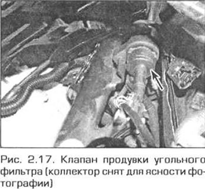
17. Disconnect the electrical connector plug from the valve, pull the valve out of the holder and disconnect the remaining hose (Fig. 2.17).
18. Install the valve in reverse order.
Engines M52TU and M54
19. The valve is located under the intake manifold. Perform the actions specified in paragraph 14.
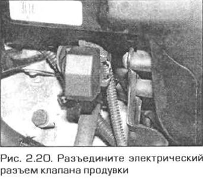
20. Disconnect the electrical connector plug from the valve under the manifold (Fig. 2.20).
21. Disconnect the hose from the bottom of the valve by pressing the latch.
22. Disconnect the remaining hose and pull the valve out of the rubber sleeve.
23. Install the valve in reverse order.
Replacing the catalytic converter
Engines M43TU and N42
24. The catalytic converter is made as a single unit with the exhaust pipe. The converter can only be replaced as a complete unit with the exhaust pipe.
Engines M52TU and M54
25. The catalytic converter is made as a single unit with the exhaust manifolds. The converter can only be replaced as a complete unit with the manifolds.
Replacing oxygen sensors
Note: The exhaust system must be completely cool before removing the oxygen sensor.
26. The oxygen sensor is screwed into the following locations.
- a) On models with the M43TU engine - before and after the catalytic converter.
- b) On models with N48 engine - before and after the catalytic converter.
- c) On models with M58TU and M54 engines - before and after the catalytic converters.
27. Turn off the ignition.
28. Apply the parking brake, lift the front of the vehicle and place it on reliable supports. Remove the crankcase guard from under the engine.
Engines M43TU and N42
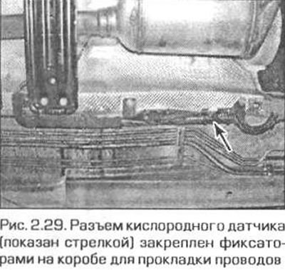
29. Trace the wiring from the sensor to the connector under the vehicle and disconnect the connector (Fig. 2.29).
Engines M52TU and M54
Note: Due to difficult access, the entire exhaust system will have to be removed to remove the cylinder sensor for cylinders 4 through 6.
30. For better access, remove the air duct for the ventilation and heating system from the rear of the engine compartment as follows.
- a) Remove the cabin filter cover by turning its latches 90° counterclockwise. Pull the filter out of the housing.
- b) Unfasten the four fasteners of the box for laying the wires and remove the sleeves with wires from the box (see fig. 8.14.a).
- c) Remove the four screws and pull the cabin filter housing forward.
- d) In the left rear corner of the engine compartment, pull off the seal, turn the two fasteners counterclockwise and move the trim panel forward slightly.
- d) Unscrew the two screws and remove the air duct (see fig. 8.14,b).
31. Remove the plastic cover over the injectors by removing the two plugs and unscrewing the screws underneath them.
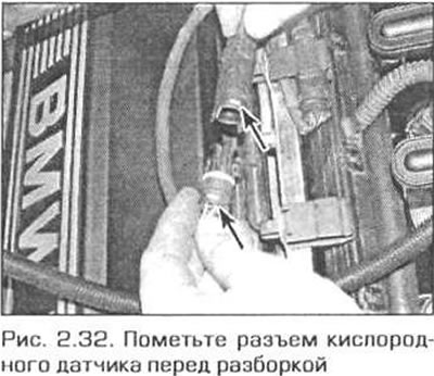
32. Release the sensor wiring from the fasteners and disconnect their connectors. Mark the connectors to avoid difficulties during installation (Fig. 2.32).
33. Remove the exhaust manifolds as described in Chapter 4A.
All models
34. Remove the oxygen sensor from the exhaust pipe.
35. The sensor is installed in the reverse order, taking into account the following notes.
- a) Tighten the sensor to the specified torque.
- b) Make sure that the wires do not touch the exhaust system.
- c) Make sure that no dirt or grease gets on the tip of the sensor.
- d) Apply a small amount of copper based grease to the sensor threads before screwing it into the exhaust pipe.
Secondary air injection system
Engine Control Valve M43TU
36. The control valve is located in the secondary air pipe on the front side of the cylinder head. Disconnect the vacuum hose from the valve.
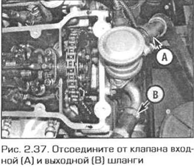
37. Compress the retaining ring and disconnect the air pump hose from the valve. Disconnect the outlet hose from the valve. Before removing, mark the hoses (Fig. 2.37)
38. Unscrew the three valve bracket mounting bolts and remove the valve together with the bracket from the cylinder head.
39. Install the valve in reverse order.
M43TU Engine Diverter Valve
40. The diverter valve is located at the front of the cylinder head. Disconnect the electrical wiring plug from the valve.
41. Remove the valve from the support bracket and disconnect the vacuum hoses from it. Note the position of the hoses (Fig. 2.41).
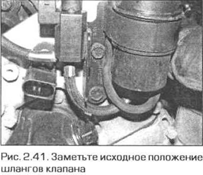
42. Install the valve in reverse order.
Engine Air Pump M43TU
43. Disconnect the electrical connector under the pump.
44. Disconnect the outlet hose from the pump by squeezing the retaining ring. The inlet hose simply needs to be pulled off the branch pipe. Remember the position of the hoses so as not to mix them up during installation (Fig. 2.44).
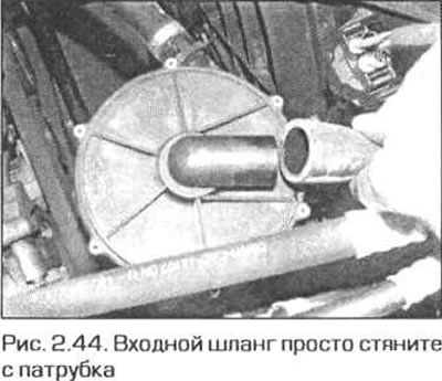
45. Remove the three bolts securing the pump to the support bracket and remove the pump.
46. Installation is carried out in reverse order.
Pressure valve engine N42
47. The pressure valve is located above the exhaust manifold on the right side of the cylinder head. Squeeze the locking ring of the pump hose connection to the valve and disconnect the hose from the valve.
48. Unscrew the two valve mounting nuts and remove it from the cylinder head (Fig. 2.48).
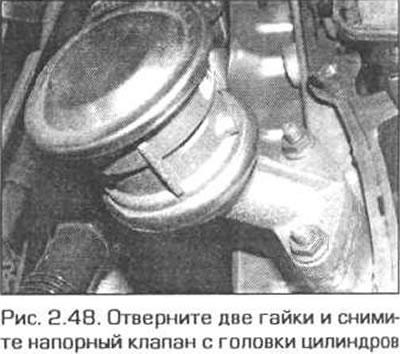
49. Install the valve in the reverse order. Securely tighten the valve mounting nuts.
Air pump engine N42
50. The air pump is located on a bracket secured with bolts to the right mudguard of the engine compartment. Squeeze the locking ring of the pump hose connection to the valve and disconnect the hose from the pump (Fig. 2.50).
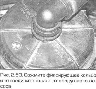
51. Cut the clamp that secures the pump inlet hose to the top of the pump and remove the hose.
52. Remove the two bolts securing the pump bracket to the mudguard bracket and remove the pump. Disconnect the electrical connector from the pump.
53. Install the pump in the reverse order of removal. Securely tighten the bracket mounting bolts.
Pressure valve engine M52TU
54. Perform the actions specified in paragraphs 47-49.
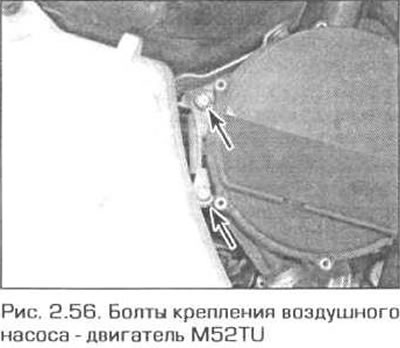
Engine Air Pump M52TU
55. The air pump is located on the right mudguard in the engine compartment. Disconnect the hose from the pump.
56. Unscrew the two bolts and remove the pump (Fig. 2.56). Disconnect the electrical connector from the pump.
This article is available at russian, bulgarian, belarusian, ukrainian, serbian, croatian, romanian, polish, slovak, hungarian
Article verified: Ilyinsky Matvey
Share information:
Previous articles
БМВ E46: Fuel and exhaust system
Next articles
Similar articles on other types of BMW cars:
Evaporative emission control system (EVAP) BMW 5 Series E28 (1981-1988)
On-Board Control System (OBCS) Unit BMW 5 Series E12 (1972-1981)
Operating principles of diesel engine control systems BMW 7 Series E38 (1994-2001)
Filter replacement BMW 7 Series E32 (1986-1994)
Control and signal lamps BMW X3 E83 (2003-2010)
Replacement of the ECU of the ABS/ASC+T and DSC systems BMW X5 E53 (1999-2006)
Link in different formats to this page
Visitor comments
No comments yet
- General information
- Manual
- Maintenance
- Power unit
- Engine repair
- Cooling system
- Power system (gasoline)
- Injection system (gasoline)
- Fuel system (diesel)
- Exhaust system
- Ignition system
- Charge and launch systems
- Transmission
- Car gearbox
- Clutch and drive shafts
- Chassis
- Brake system
- Suspension front and rear
- Steering
- Body
- Body care and repair
- Exterior
- Interior
- Electrical equipment
- Troubleshooting
- Lighting and signaling
- Equipment and devices
- Heater and air conditioner
- Electrical circuits
- General information
- Manual
- Repair on the road
- Weekly checks
- Maintenance
- Troubleshooting
- Power unit
- 4 cylinder engines
- 6 cylinder engines
- Engine overhaul
- Cooling and heating
- Fuel and exhaust system
- Starting and charging system
- Ignition system
- Transmission
- Clutch
- Mechanical gearbox
- Automatic gearbox
- Cardan and drive shafts
- Chassis
- Brake system
- Wheel suspension
- Steering
- Body
- Exterior
- Interior
- Electrical equipment
- Equipment and devices
- Electrical circuits
- General information
- Maintenance
- Power unit
- Engine repair
- Cooling system
- Ignition system
- Supply system
- Fuel injection system
- Exhaust system
- Transmission
- Clutch
- Car gearbox
- Front and rear axle
- Chassis
- Steering
- Brake system
- Body
- Exterior
- Interior
- Electrical equipment
- Heating system
- Equipment and devices
- Power devices
- Electrical circuits
- Power unit
- M10/M20 engine
- M40 engine
- Ignition system
- Lubrication system
- Cooling system
- Supply system
- Fuel injection
- Exhaust system
- Transmission
- Clutch
- Manual gearbox
- Front axle
- Rear axle
- Chassis
- Steering
- Brake system
- Body
- Exterior
- Interior
- Electrical equipment
- Heating system
- Equipment and devices
- Electrical circuits
- General information
- Specifications
- Operation and maintenance
- 4-cylinder engine
- Engine repair
- Cooling and lubrication system
- Supply system
- Ignition system
- 6-cylinder engine
- Engine repair
- Cooling and lubrication system
- Supply system
- Fuel injection system
- Ignition system
- Transmission
- Clutch
- 4-speed manual gearbox
- 5-speed manual gearbox
- Automatic gearbox
- Cardan and rear axle
- Chassis
- Steering
- Front suspension
- Rear suspension
- Brake system
- Electrical equipment
- Equipment and devices
- Electrical circuits