
Warning! Observe safety precautions for protection against electrostatic discharge. Use grounding wrist straps.
Removal of the ECU of the "ABS/ASC+T" and "DSC" systems must be carried out in the following order. Read information from the fault memory and print out fault codes. On cars with the "M62" and "N62" engines, remove the left headlight and control panel.
If necessary, disconnect the additional heating system pump. Disconnect the HS and move the additional pump to the side, securing it to the body. Unlock the HS by sliding its lock and remove the HS by pulling it vertically upward.
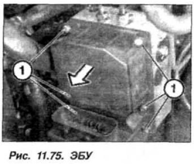
Remove the bolts (1, Fig. 11.75) and disconnect the ECU (2) from the GA. The bolts must be replaced.
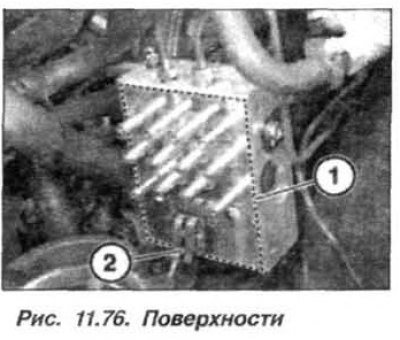
The installation of the ECU of the ABS/ASC+T/DSC system on the hydraulic unit should be carried out in the reverse order, while it is necessary to visually check the sealing surface of the ECU (1, Fig. 11.76) ECU and GA for damage. Clean the sealing surfaces (1), do not use tools with sharp edges or aggressive cleaning agents. Check the contact petals (2) for corrosion and damage. If damage is detected on elements (1) and (2), the GA must be replaced.
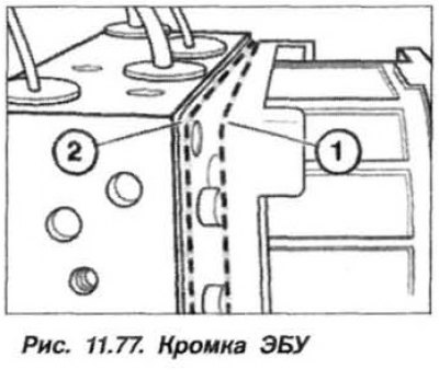
To avoid damaging the contact pins of the HS-ECU, insert the HS into the ECU, holding it strictly perpendicular to the ECU. Carefully place the ECU on the GA. Avoid distorting the excitation coils. The edge of the ECU housing (1, Fig. 11.77) should slide along the ledge (2) of the GA.
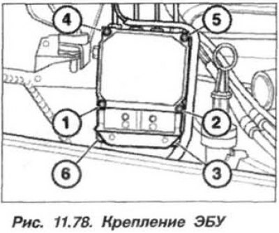
Press the ECU to the GA and screw in new bolts evenly (1 and 2, Fig.11.78), slowly tightening them until the ECU housing is evenly pressed against the hydraulic cylinder. Screw in new bolts (1–6) until the contact surfaces are pressed together, without tightening them completely. Tighten the ECU mounting bolts with a torque wrench to 2.9 N·m (0.29 kgf·m) in the sequence shown in Figure 11.78. Check the fixation of the ECU SS.
After installing a new ECU, it must be coded. If the "DSC" system is present, additionally match the steering wheel position sensor using the "DIS" system.