
Attention! When disconnecting the battery and disconnecting the control system, the faults entered during vehicle operation are erased in the ECU-KSUD.
Do not mix up the brake drive pipes when connecting to the hydraulic unit.
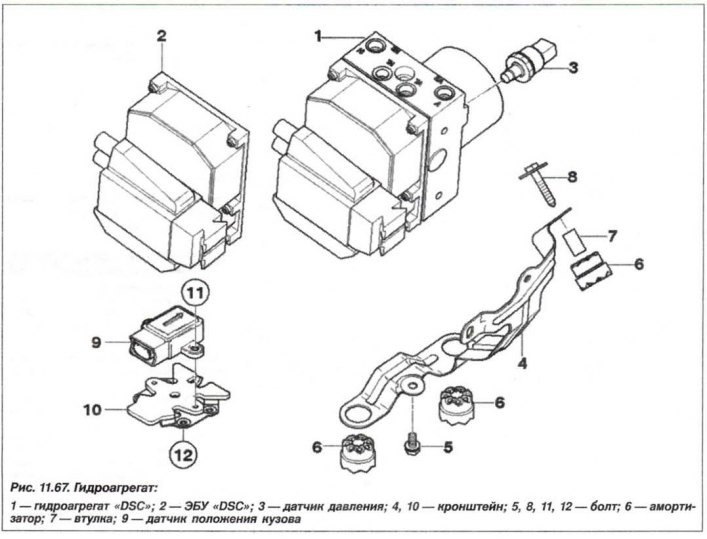
The design of the hydraulic unit (HU) and its installation bracket are shown in Figure 11.67.
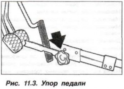
The removal of the "DSC" system GA must be carried out in the following order. Read information from the ECU fault memory, print out the fault code if necessary and eliminate the faults. Switch off the ignition and remove the "–" terminal from the battery. Press the brake pedal and lock it with the stop (Fig. 11.3).
On a car with an M62 engine, remove the instrument panel; on a car with an M54 engine, remove the air filter housing. If necessary, disconnect the heater coolant pump with the bracket and secure them with a wire clip to the body. Disconnect the ECU "ABS/ASC+T" ("DSC") connection loop to the hydraulic cylinder and its ground wire (jumper) from the car body.
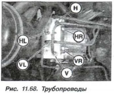
Mark the hydraulic pipeline connection points with tags (markers) (fig. 11.68) to the GA, so as not to mix them up when installing. Disconnect the pipelines from the GA. Close the pipelines and block fittings with plugs/caps.
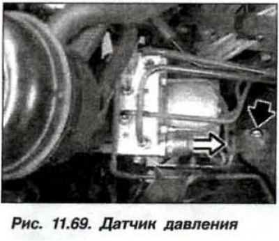
Unlock and disconnect the SS from the pressure sensor (light arrow, Fig. 11.69).
Loosen the mounting bolts and remove the GA. Loosen the bolts (8, see Fig. 11.67) and remove the mounting bracket (4) from the GA.
The installation of the "DSC" system GA should be carried out in the reverse order, while the bolt securing the GA bracket to the body must be tightened to a torque of 8.0 N·m (0.8 kgf·m).
Pipeline installation locations (see fig. 11.68):
- V-front wheels, from THZ contour V to GA contour V (front wheel brake drive circuit);
- H-rear wheels, from TNZ circuit H to GA H (rear wheel brake drive circuit;
- VR-front left wheel, from GA VR front left wheel to brake mechanism VR;
- VL-front left wheel, from HA HR to brake mechanism HR wheel;
- HL-rear left wheel, from HA HL to brake mechanism HL wheel.
Tighten the pipe fittings to a torque of 14 N·m (1.4 kgf·m). Tighten the bracket mounting bolts on the hydraulic system to a torque of 8.0 N·m (0.8 kgf·m).
Use the "DIS-BMW" system to check:
- operation of the hydroelectric unit;
- coding, when replacing the ECU;
- steering wheel position sensor corrections;
- upon completion of assembly, when replacing the ECU.
Pay special attention to subsequent bleeding of the brake system and the reliability of the connection of the ground terminals.