
Electronic control unit
1. Disconnect the negative battery cable.
Note. Disconnecting the battery will lead to the disappearance of all fault codes from the memory of the BEU. It is recommended that before disconnecting the battery, check for codes using special diagnostic equipment. Leave this work to the dealer or a specialist who has such equipment.
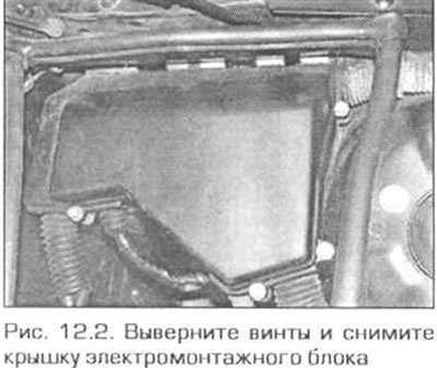
2. In the left corner of the engine compartment, unscrew the four screws and remove the cover of the electrical box (pic. 12.2).
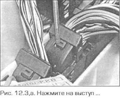
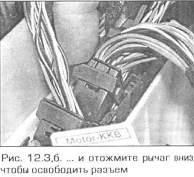
3. Disconnect the connector plugs from the BEU and pull it out of the wiring block (pic. 12.3, a, b).
4. Installation is carried out in the reverse order.
Note. If the BEU has been replaced, it must be encoded using special equipment. Have this work carried out by a BMW dealer or a specialist who has such equipment. After connecting the battery, drive the car for several kilometers so that the ECU "learned" all presets. If the engine still runs intermittently after this, the initial settings can be changed by the dealer or a qualified technician.
Fuel rail and injectors
Attention! Read the warnings about paragraph 1 before starting this work.
5. Relieve the pressure in the fuel system (see paragraph 8), then disconnect the negative battery cable.
M43TU engine
Note. At installation it is necessary to replace sealing rings of atomizers.
6. Remove the upper section of the intake manifold as directed in paragraph 13.
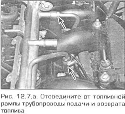
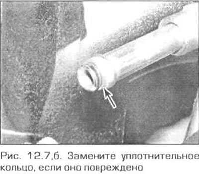
7. On the fuel rail, loosen the clamp and disconnect the fuel return hose, then unscrew the union nut and disconnect the pressure fuel line (pic. 12.7, a, b). Be prepared for fuel to pour out of the holes and take precautions. Plug the openings in the ramp and in the pipes so that dirt does not creep into the system.
8. Disconnect the vacuum hose from the rail pressure regulator 8.
9. Disconnect the electrical wiring from the injectors and remove the injector wiring harness, releasing it from the fasteners.
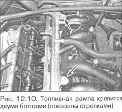
10. Remove the two bolts that secure the ramp to the exhaust manifold (pic. 12.10).
11. Carefully remove the rail up so that the injectors come out of the manifold, then remove the rail along with the injectors from the engine.
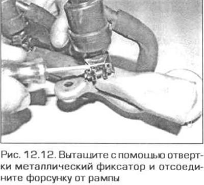
12. To separate the injectors from the fuel rail, follow these steps.
- A) Pull out the metal retainer of the injector with a screwdriver (pic. 12.12).
- b) Pull the injector out of the fuel rail.
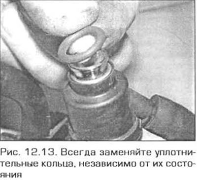
13. Before installing the injectors, replace all o-rings, regardless of their condition (pic. 12.13).
14. Make sure there are plastic washers under the lower injector o-rings.
15. Lubricate the O-rings with a small amount of petroleum jelly or 90 SAE gear oil.
16. Insert the nozzles into the fuel rail and secure them with clamps. The nozzles must be inserted like this. so that after the ramp is installed in place, their electrical connectors are on top.
17. Reinstall the rail with the nozzles, being careful. so that the injectors go into their holes in the manifold.
18. The rest of the installation is performed in the reverse order of removal. Install the upper section of the intake manifold as directed in paragraph 13. Fill the system with fuel (insert the fuel pump fuse and turn on the ignition). Check for fuel leaks before starting the engine.
N42 engine
19. Turn out two nuts, lift a front edge of a plastic cover over the engine and pull it forward.
20. At the rear of the engine compartment, remove the cabin filter cover by turning its retainers 90°counterclockwise. Pull the filter out of the housing.
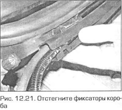
21. Unfasten the latches and remove the wires from the box (pic. 12.21).
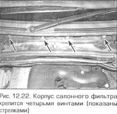
22. Remove the four screws and pull the cabin filter housing forward (pic. 12.22).
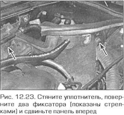
23. In the left rear corner of the engine compartment, pull off the seal, turn the two latches and move the trim panel slightly forward (pic. 12.23).
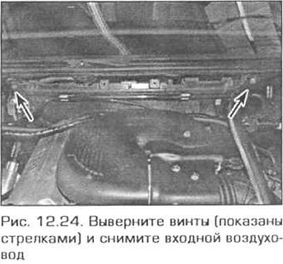
24. Turn out two screws and remove an entrance air duct of a heater (pic. 12.24).
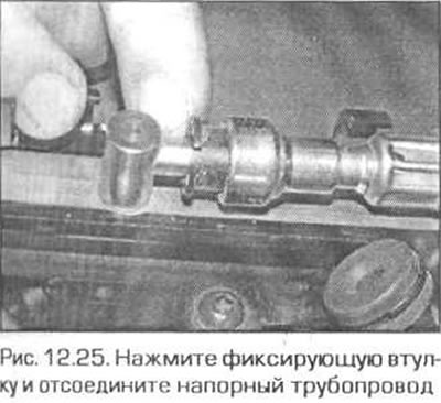
25. Press inside the fixing sleeve and disconnect the fuel supply pipe from the fuel rail. Be prepared for fuel to leak from the openings and take appropriate precautions. Plug the holes with plugs to keep dirt out of the system (pic. 12.25).
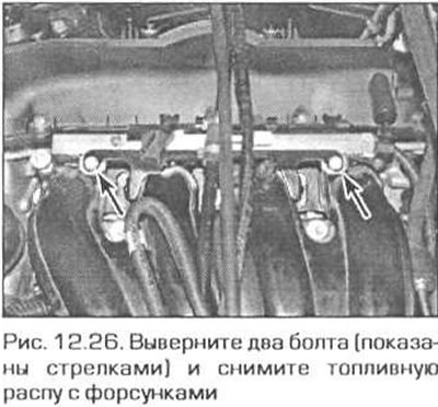
26. Unhook the cable, unscrew the two nuts securing the bracket to the cylinder head, then unscrew the two bolts securing the fuel rail and remove the rail together with the injectors (pic. 12.26).
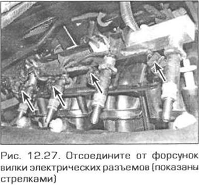
27. Disconnect the electrical wiring from the injectors. If necessary, cut the wire harness clamps and release them from the fuel rail (pic. 12.27).
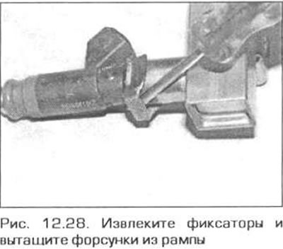
28. Remove the clips and pull the nozzles out of the rail (pic. 12.28).
29. Lubricate the injector O-rings with a small amount of petroleum jelly or acid-free grease.
30. Insert the nozzles into the fuel rail and secure them with clamps.
31. The rest of the installation is performed in the reverse order of removal.
M52TU engine
32. Follow the steps indicated in p.p. 20-24.
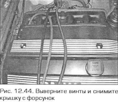
33. Pull out the plugs, unscrew the screws and remove the cover over the nozzles (see fig. 12.44).
34. Disconnect the vacuum hose from the fuel pressure regulator.
35. Disconnect the electrical connector of the inlet air temperature sensor and remove the box with wires from the injectors.
36. Label the two oxygen sensor connectors. to avoid mixing them up during installation, separate the connectors and release them from the latches.
37. Mark the pressure and return pipelines and disconnect them from the ramp.
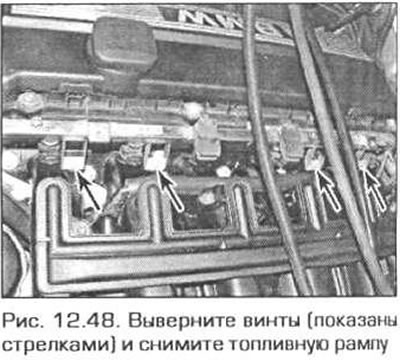
38. Turn out four screws and remove a fuel stage together with atomizers (see fig. 12.48).
39. To separate the injectors from the fuel rail, follow these steps.
- A) Remove the injector clips with a screwdriver.
- b) Pull the injectors out of the rail.
40. Lubricate the injector O-rings with a small amount of petroleum jelly or acid-free grease.
41. Insert the nozzles into the fuel rail and secure them with clamps.
42. The rest of the installation is performed in the reverse order of removal.
M54 engine
43. Follow the steps indicated in p.p. 20-24.
44. Pull out the plugs, remove the screws and remove the cover over the nozzles (pic. 12.44).
45. Label the two oxygen sensor connectors. to avoid mixing them up during installation, separate the connectors and release them from the latches.
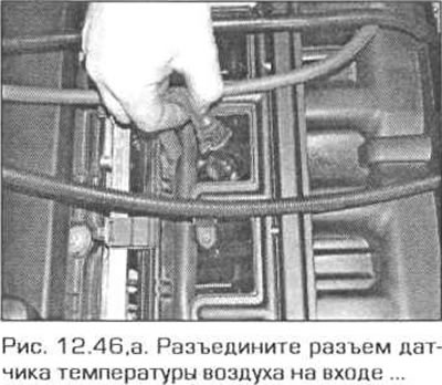
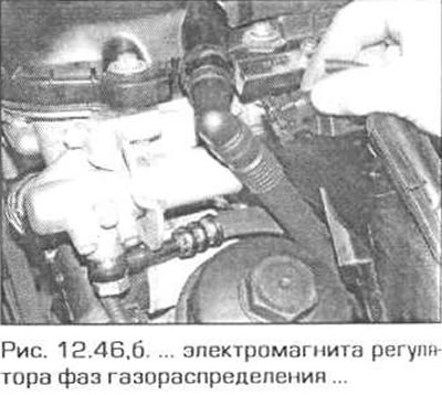
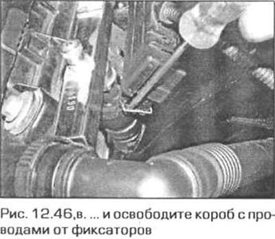
46. Disconnect the electrical connector of the inlet air temperature sensor, the connector of the electromagnet of the valve timing regulator VAN0S and remove the box with wires from the injectors (pic. 12.46 a-c).
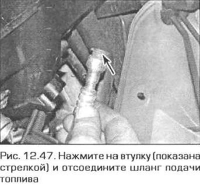
47. Disconnect the fuel supply hose from the rail (pic. 12.47).
48. Remove the four screws and remove the fuel rail along with the injectors (pic. 12.48).
49. To separate the injectors from the fuel rail, follow these steps.
- A) Remove the injector clips with a screwdriver.
- b) Pull the injectors out of the rail.
50. Lubricate the injector O-rings with a small amount of petroleum jelly or acid-free grease.
51. Insert the nozzles into the fuel rail and secure them with clamps.
52. The rest of the installation is performed in the reverse order of removal.
Fuel pressure control
Attention! Please read the warning in paragraph 1 before starting this work.
53. Relieve the pressure in the fuel system (see paragraph 8), then disconnect the negative battery cable.
M43TU engine
Note. New o-rings are required for installation.
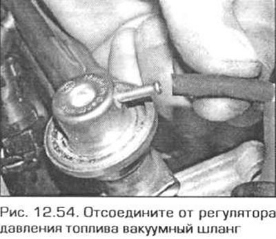
54. Disconnect the vacuum hose from the regulator (pic. 12.54).
55. To improve access, disconnect the crankcase ventilation hose from the cylinder head cover.
56. Note the position of the vacuum hose on the regulator in order to install it in the same position later.
57. To provide sufficient space for removing the regulator, remove the lifting eye from the cylinder head.
58. On models where the regulator is attached with a bracket screwed on with a nut, unscrew the nut and remove the bracket.
59. On models where the regulator is secured with a retainer, remove the retainer.
60. Turning the regulator, pull it out of the ramp. The regulator is difficult to pull out of the ramp because of the o-rings.
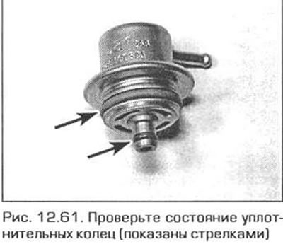
61. Before installing the regulator into the rail, check the condition of the sealing rings, and if necessary, replace (pic. 12.61).
62. Installation of the regulator is carried out in the reverse order.
N42 engine
63. On this engine, the pressure regulator is built into the fuel filter.
64. If the regulator fails, replace the filter assembly.
M52TU engine
65. To expand the working space, remove the inlet air duct of the heating and ventilation system from the rear side of the engine compartment as follows.
- A) Turn 90°counterclockwise the three retainers of the cabin air filter cover and remove the cover. Pull out the filter.
- b) Unfasten the cable routing box latches and remove the wiring from the cable box (see fig. 12.21)
- V) Remove the four screws securing the cabin filter housing and pull out the housing.
- G) Remove the two screws and pull the air duct up (see fig. 12.24).
66. Remove the cover from the fuel rail, for which remove the plugs and unscrew the two screws securing it.
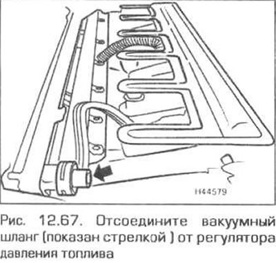
67. Disconnect the vacuum hose from the fuel pressure regulator (pic. 12.67).
68. Remove the spring clip and pull the regulator out of the fuel rail while turning it.
69. Inspect O-rings prior to installation and replace if necessary.
70. Installation of the regulator is carried out in the reverse order, taking into account the following remarks.
- A) Make sure. that the regulator is fully inserted and securely held in the fuel rail.
- 6) Fasten the regulator securely with the spring clip.
- V) Finally fill the fuel system (insert the fuel pump fuse and turn on the ignition. Check disturbed areas for leaks.
M54 engine
71. On these engines, the pressure regulator is structurally combined with the fuel filter. If the regulator fails, the filter assembly must be replaced.
Air flow sensor
M43TU engine
Note. During reassembly, the sensor seal may need to be replaced.
72. Disconnect the negative battery cable.
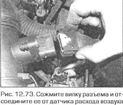
73. Disconnect the electrical connector of the air flow sensor (pic. 12.73).
74. Loosen the clamp and disconnect the air duct from the flow sensor.
75. Release the sensor from the clamps and remove the air flow sensor.
76. Installation of the sensor is carried out in the reverse order. Inspect the gasket and if damaged, replace.
N42 engine
77. Disconnect the negative battery cable.
78. Loosen the clamp and disconnect the inlet duct and resonance chamber from the air cleaner.
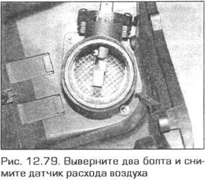
79. Remove the two nuts and remove the air flow sensor from the air cleaner.
80. Installation is carried out in reverse order.
M52TU engine
Note. During reassembly, the sensor seal may need to be replaced.
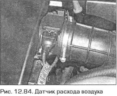
81. Turn off the ignition. Disconnect the electrical connector from the sensor (see fig. 12.84).
82. Disconnect the vacuum hose from the intake duct, remove the sensor together with the intake duct.
83. Installation is carried out in reverse order. Check the condition of the seal and. replace if necessary.
M54 engine
Note. During reassembly, the sensor seal may need to be replaced.
84. Turn off the ignition. Disconnect the electrical connector from the sensor (fig 12.84).
85. Release the clamp and disconnect the inlet duct from the sensor. Remove the sensor from the air cleaner.
86. Installation is carried out in reverse order. Check the condition of the seal and. replace if necessary.
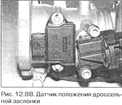
Throttle position sensor
M43TU engine
Note. During reassembly, the O-ring may need to be replaced.
87. Turn off the ignition.
88. Disconnect the electrical connector from the sensor (fig 12.88).
89. Turn out two screws of fastening of the gauge and remove it from the throttle body.
90. Installation is carried out in reverse order. Check the condition of the O-ring and replace if necessary. Sensor adjustment is not required.
N42 engine
91. On this engine, the throttle valve is electrically actuated by the signal from the accelerator pedal position sensor. The electric throttle actuator is integral with the damper body. Removal of the throttle body is described in paragraph 11. The accelerator pedal position sensor is integral with the pedal. Removing the pedal is described in paragraph 8.
M52TU and M54 engines
92. The throttle position sensor is integral with the throttle body. Removal of the damper body is described in paragraph 11.
93. Installation is performed in sequence. reverse withdrawal. Keep in mind: if a new damper body with a position sensor is installed, then all parameter values adapted to the old body must be deleted from the ECU memory. This work can be done by a BMW dealer or specialists from a branded service station. After deleting the old information, the BEU will determine and remember the new parameters during the operation of the vehicle.
Coolant temperature sensor
M43TU engine
94. The sensor is located on the left side of the cylinder head. Partially drain the coolant and remove the upper section of the intake manifold (see paragraph 13).
95. Turn out the gauge from a head of cylinders.
96. Installation is carried out in reverse order. Tighten the sensor to the required torque. Fill the cooling system.
N42 engine
97. The sensor is located on the left side of the cylinder block. Partially drain the coolant.
98. Remove the alternator as directed in chapter 5A.
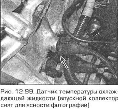
99. Disconnect the wiring from the sensor and unscrew the sensor from the cylinder block (pic. 12.99).
100. Installation is carried out in reverse order. Tighten the sensor to the required torque. Fill the cooling system.
M52TU and M54 engines
101. The sensor is located on the left side of the cylinder head, under the intake manifold. Partially drain the coolant and remove the intake manifold (see paragraph 13).
102. Disconnect the wiring from the sensor and unscrew the sensor from the cylinder block.
103. Installation is carried out in reverse order. Tighten the sensor to the required torque. Fill the cooling system.
Crankshaft position sensor
M43TU engine
104. Raise the front of the car and place it on secure supports. Remove the engine crankcase protection.
105. The sensor is located under the starter. Disconnect the electrical connector from the sensor, remove the sensor mounting screw and remove the sensor.
106. Installation is carried out in reverse order. Check the condition of the seal and replace if necessary.
N42 engine
107. The sensor is located under the starter. Remove the intake manifold as directed in paragraph 13.
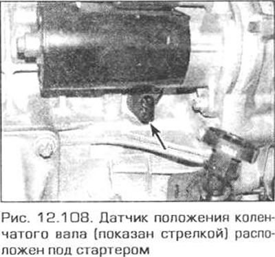
108. Disconnect the electrical connector from the sensor, unscrew the sensor mounting screw and remove the sensor (pic. 12.108).
109. Check the condition of the sealing ring and, if necessary, replace it. Reinstall the sensor and tighten its fastening screw to the required torque.
110. The rest of the installation is carried out in the reverse order of removal.
M52TU engine
111. Follow the steps specified in p.p. 104-105.
M54 engine
112. Raise the front of the car and place it on secure supports. Remove the engine crankcase protection.
113. Remove the booster between the lower suspension arms. Keep in mind that when installing the amplifier, the bolts of its fastening must be replaced.
114. The sensor is located under the starter. Disconnect the electrical connector from the sensor, remove the sensor mounting screw and remove the sensor.
115. Installation is performed in sequence. reverse withdrawal. When installing the amplifier, replace the bolts with new ones.
Sensor (And) distributive provisions (s) shaft (ov)
M43TU engine
116. The sensor is located on the top cover of the camshaft drive chain.
117. Turn off the ignition and disconnect the sensor electrical connector.
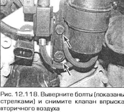
118. To facilitate access to the sensor, unscrew the bolts securing the secondary air injection solenoid valve and the bracket and move them to the side (pic. 12.118).
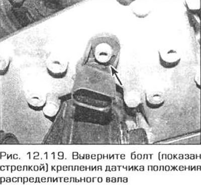
119. Turn out a bolt of fastening of the gauge and remove it from the engine (pic. 12.119).
120. Check up a condition of a sealing ring and. replace if necessary.
121. Install the sensor in place and securely fasten it with a bolt.
122. The rest of the installation is carried out in the reverse order of removal.
N42 engine
123. Sensors are located on the front side of the cylinder head under the ends of the respective camshafts. Switch off the ignition.
124. Remove the two clips and remove the casing from the front transverse panel of the engine compartment.
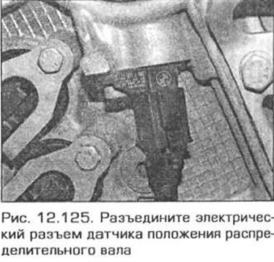
125. Disconnect the electrical connector of the sensor (squeeze the tabs) (pic. 12.125).
126. Turn out a bolt of fastening of the gauge and remove the gauge from the engine.
127. Installation of the sensor is carried out in the reverse order. Check the condition of the seal and replace if necessary.
Intake camshaft (engines M52TU and M54)
128. Turn off the ignition. Remove the air cleaner (see paragraph 2).
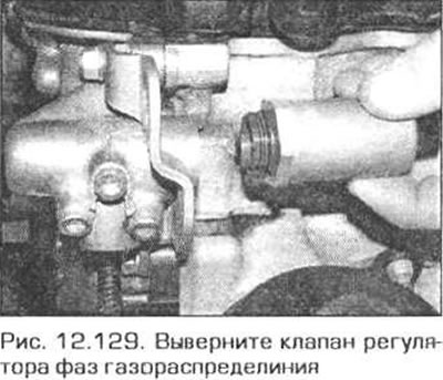
129. To access the sensor, disconnect the electrical connector from the VANOS camshaft control valve solenoid and unscrew the valve (pic. 12.129).
130. Trace the sensor wires and disconnect the electrical connector there. where it is attached to the wiring box behind the generator.
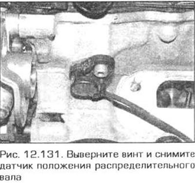
131. Remove the sensor mounting screw and remove the sensor from the cylinder head (pic. 12.131).
Exhaust camshaft (engines M52TU and M54)
132. Turn off the ignition.
133. Disconnect the electrical connector of the sensor, remove the mounting screw and remove the sensor (pic. 12.133).
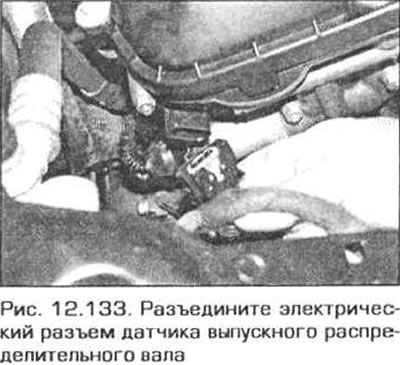
134. Installation is performed in sequence. reverse withdrawal. Check the condition of the seal and replace if necessary.
Oxygen sensor
135. See chapter 46.
Idle valve
M43TU engine
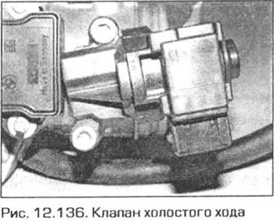
136. The valve is located outside on the throttle body (pic. 12.136).
137. Turn off the ignition.
138. Separate an electric socket of the valve.
139. Disconnect the vacuum hose from the valve.
140. Remove the two screws securing the valve and remove it from the damper body
141. Installation is carried out in reverse order. Clean the valve seat. Check the condition of the seal and. if necessary, replace it.
N42 engine
142. On this engine, idling is regulated by the rise and duration of the opening of the intake valves, controlled by the electronic engine control unit
M52TU and M54 engines
143. Disconnect the negative battery cable.
144. The idle valve on these engines is located under the intake manifold and above the throttle body.
145. Remove the air cleaner (see paragraph 2).
146. Pull the accelerator cable sheath out of the bracket on the throttle body.
147. Release clips and disconnect an air line from the throttle body and from the valve of idling.
148. Disconnect the electrical connectors for the idle air valve and the intake manifold flap control valve.
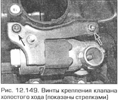
149. Turn out a nut of fastening of an arm of a cable and two screws of fastening of an arm of the valve of idling. Remove valve from intake manifold (pic. 12.149). The gasket between the valve and the manifold can be discarded - a new gasket is needed for installation.
150. Lubricate a new gasket with grease and apply it to the intake manifold. Reinstall the idle air valve, and securely tighten the support bracket fasteners.
151. The rest of the installation is carried out in the reverse order of removal.
Fuel pump turnip
152. Disconnect the negative battery cable.
153. Remove the glove box on the passenger side as described in Chapter 11, paragraph 27.
154. Insert a flathead screwdriver into the slot of the glove box light socket and pry the socket out. Disconnect the cartridge from the wiring as soon as the electrical connector appears.
155. Remove the five screws, remove the retainer and remove the drawer frame from the front panel (if necessary, see chapter 11 for more information).
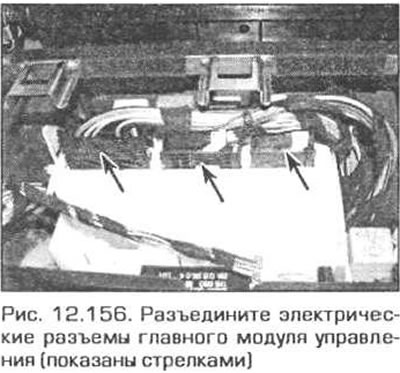
156. Disconnect the electrical connectors from the main control module (pic. 12.156).
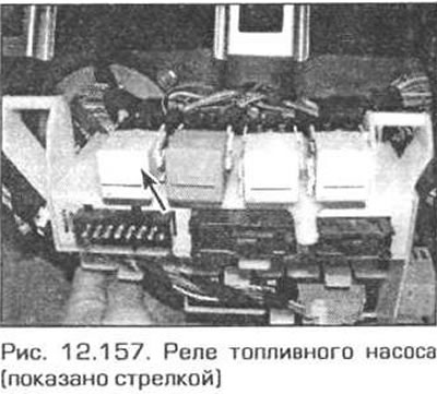
157. Pull the fuel pump relay out of the burr board (pic. 12.157).
158. Install the relay in reverse order.
Main control system relay
159. Turn off the ignition.
160. In the left corner of the engine compartment, unscrew the four screws and remove the cover of the electrical box (see fig. 12.2).
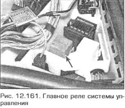
161. Pull the relay out of the socket (pic. 12.161).
162. Installation is carried out in the reverse order.
Accelerator pedal position sensor
N42 engine
163 The pedal position sensor is structurally integrated with the pedal assembly. Removing the pedal is described in paragraph 6.
Intake manifold pressure sensor
164. Turn off the ignition. Loosen the two nuts, lift the front edge of the cover over the engine and pull it forward.
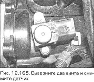
165. Disconnect the plug of the electrical connector from the sensor, unscrew the screws that secure the sensor and remove it from the manifold (pic. 12.165).
166. Installation of the sensor is carried out in the reverse order.