
- Home
- BMW 3 Series
- E46
- Power unit
- Fuel and exhaust system
- Throttle body — removal and installation
Throttle body — removal and installation (BMW 3 Series E46)
Engine M43TU
Note: When installing, it is necessary to replace the gasket under the throttle body.
Removal
1. Disconnect the negative battery cable.
2. Loosen the screws and remove the cover from the throttle body.
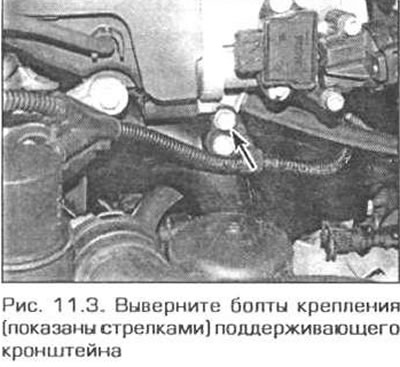
3. Unscrew the bolts securing the bracket to the throttle body (Fig. 11.3).
4. Disconnect the electrical connectors of the throttle position sensor and idle air control valve.
5. Disconnect the accelerator cable from the throttle lever and remove it from the support bracket (see fig. 5.2 and 5.3). If there is also a cruise control cable, disconnect it in the same way.
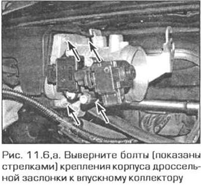
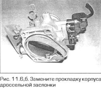
6. Remove the four bolts securing the throttle body to the intake manifold and remove the body from the manifold. Remove the gasket between the throttle body and the manifold (fig. 11.6,a,b).
Installation
7. Installation is carried out in the reverse order of removal, taking into account the following notes.
- a) Install a new gasket between the throttle body and the intake manifold.
- b) Connect and, if necessary, adjust the accelerator cable (see paragraph 5).
- c) Finally, allow the specialist to check for fault codes in the self-diagnostic system memory and delete them if there are no more faults.
Engine N42
Removal
8. Remove the air cleaner (see paragraph 2).
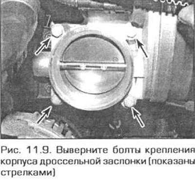
9. Disconnect the electrical connector, unscrew the four bolts and remove the throttle body (Fig. 11.9).
Installation
10. Check the condition of the sealing ring between the throttle body and the intake manifold. If it is in good condition, it can be used again. Install the throttle body onto the intake manifold, and tighten its bolts securely.
11. Connect the electrical connector and install the air cleaner.
12. Finally, allow the specialist to check for fault codes in the self-diagnostic system memory and delete them if there are no more faults.
Engine M52TU
Removal
13. Disconnect the negative battery cable.
14. Remove the air cleaner (see paragraph 2).
15. Remove the air duct with the air flow sensor (see paragraph 12).
16. Disconnect the cable from the throttle sector and release it(them) from the bracket.
17. Disconnect the air duct from the throttle body and the idle air valve.
18. Disconnect all electrical connectors from the damper body.
19. Disconnect the wiring from the emergency pressure and emergency oil temperature sensors near the oil filter.
20. Release the fuel lines and vacuum hose from the bracket on the oil dipstick tube.
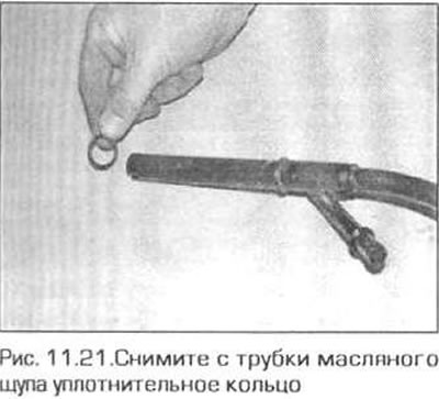
21. Disconnect the oil return tube from the dipstick tube, unscrew the dipstick tube mounting bolt and remove it from the engine. The tube sealing ring can be discarded - it must be replaced during installation (fig. 11.21).
22. Remove the three screws/nuts securing the cable box.
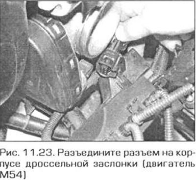
23. On the M52TU engine, turn the electrical connector ring on the throttle body and disconnect the connector. On the M54 engine, release the connector lock and disconnect the connector (fig. 11.23). Remove the four screws securing the valve body to the intake manifold and remove the body.
Installation
24. Check the condition of the sealing ring between the throttle body and the intake manifold. If it is in good condition, it can be used again. Install the throttle body onto the intake manifold and tighten its bolts securely.
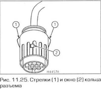
25. Before connecting the electrical connector of the throttle body on the M52TU engine, rotate its ring so that the red dowel pin is visible in the window of the ring. Align the arrow on the ring with the arrow on the connector socket and insert the plug into the socket. Rotate the connector ring clockwise so that the second arrow on the ring aligns with the arrow on the socket (fig. 11.25). On the M54 engine, simply plug the plug into the socket.
26. The rest of the installation is carried out in the reverse order of removal. Note that if the throttle body has been replaced, the settings corresponding to the engine characteristics and stored in the ECU memory must be changed. This can be done by the dealer or a specialist who has the appropriate equipment at his disposal.
Engine M54
Removal
27. Disconnect the negative battery cable.
28. Remove the air cleaner (see paragraph 2).
29. Disconnect the electrical connector, disconnect the vacuum hose and remove the air cleaner connecting duct.
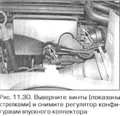
30. Loosen the two screws securing the intake manifold configuration adjustment unit, disconnect its electrical connector and remove the unit from the manifold (fig. 11.30).
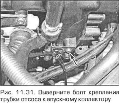
31. Unscrew the bolt securing the suction pipe to the intake manifold (fig. 11.31).
32. Loosen the clamps and disconnect the air ducts from the throttle body and from the idle air valve.
33. Disconnect the idle air control valve electrical connector.
34. Disconnect the electrical connectors of the emergency pressure and emergency oil temperature sensors near the oil filter.
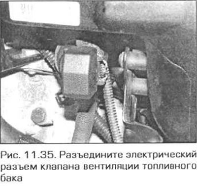
35. Press the release button and disconnect the fuel tank vent valve electrical connector plug (fig. 11.35).
36. Next, follow the steps specified in paragraphs 24-26.
[This publication was borrowed from an online resource «bmwman.ru»]
This article is available at russian, bulgarian, belarusian, ukrainian, serbian, croatian, romanian, polish, slovak, hungarian
Article verified: Ilyinsky Matvey
Share information:
Previous articles
БМВ E46: Fuel and exhaust system
Next articles
Similar articles on other types of BMW cars:
Removal and installation the throttle valve pipe BMW 5 Series E39 (1995-2003)
Removal and installation the oil pan BMW 5 Series E12 (1972-1981)
Throttle body — removal and installation BMW 7 Series E32 (1986-1994)
Removal and installation the pipe between the air flow meter and the… BMW 7 Series E38 (1994-2001)
Pistons — removal and installation BMW X3 E83 (2003-2010)
Removal and installation the engine BMW X5 E53 (1999-2006)
Link in different formats to this page
Visitor comments
No comments yet
- General information
- Manual
- Maintenance
- Power unit
- Engine repair
- Cooling system
- Power system (gasoline)
- Injection system (gasoline)
- Fuel system (diesel)
- Exhaust system
- Ignition system
- Charge and launch systems
- Transmission
- Car gearbox
- Clutch and drive shafts
- Chassis
- Brake system
- Suspension front and rear
- Steering
- Body
- Body care and repair
- Exterior
- Interior
- Electrical equipment
- Troubleshooting
- Lighting and signaling
- Equipment and devices
- Heater and air conditioner
- Electrical circuits
- General information
- Manual
- Repair on the road
- Weekly checks
- Maintenance
- Troubleshooting
- Power unit
- 4 cylinder engines
- 6 cylinder engines
- Engine overhaul
- Cooling and heating
- Fuel and exhaust system
- Starting and charging system
- Ignition system
- Transmission
- Clutch
- Mechanical gearbox
- Automatic gearbox
- Cardan and drive shafts
- Chassis
- Brake system
- Wheel suspension
- Steering
- Body
- Exterior
- Interior
- Electrical equipment
- Equipment and devices
- Electrical circuits
- General information
- Maintenance
- Power unit
- Engine repair
- Cooling system
- Ignition system
- Supply system
- Fuel injection system
- Exhaust system
- Transmission
- Clutch
- Car gearbox
- Front and rear axle
- Chassis
- Steering
- Brake system
- Body
- Exterior
- Interior
- Electrical equipment
- Heating system
- Equipment and devices
- Power devices
- Electrical circuits
- Power unit
- M10/M20 engine
- M40 engine
- Ignition system
- Lubrication system
- Cooling system
- Supply system
- Fuel injection
- Exhaust system
- Transmission
- Clutch
- Manual gearbox
- Front axle
- Rear axle
- Chassis
- Steering
- Brake system
- Body
- Exterior
- Interior
- Electrical equipment
- Heating system
- Equipment and devices
- Electrical circuits
- General information
- Specifications
- Operation and maintenance
- 4-cylinder engine
- Engine repair
- Cooling and lubrication system
- Supply system
- Ignition system
- 6-cylinder engine
- Engine repair
- Cooling and lubrication system
- Supply system
- Fuel injection system
- Ignition system
- Transmission
- Clutch
- 4-speed manual gearbox
- 5-speed manual gearbox
- Automatic gearbox
- Cardan and rear axle
- Chassis
- Steering
- Front suspension
- Rear suspension
- Brake system
- Electrical equipment
- Equipment and devices
- Electrical circuits