
- Home
- BMW 3 Series
- E46
- Power unit
- Fuel and exhaust system
- Collectors — removal and installation
Collectors — removal and installation (BMW 3 Series E46)
Upper section of the intake manifold
Engine M43TU
Note: Installation will require a new manifold gasket and new pressure control valve o-rings.
1. Turn off the ignition.
2. To improve access, remove the air inlet duct for the ventilation and heating system from the rear of the engine compartment as follows.
- a) Remove the cabin filter cover by turning its latches 90° counterclockwise. Pull the filter out of the housing.
- b) Unfasten the clamps and remove the wires from the box (see fig. 12.21).
- c) Unscrew the four screws and pull the cabin filter housing forward (see fig. 12.22).
3. Disconnect the accelerator cable from the throttle body as described in paragraph 5. Disconnect the cruise control cable (if equipped) in the same manner.
4. Loosen the clamps and remove the air inlet duct together with the air flow sensor. Disconnect the electrical connector plug from the air flow sensor and the vacuum hose from the air duct.
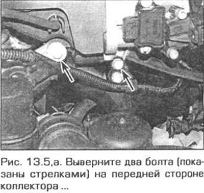
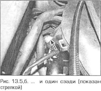
5. Remove the two bracket mounting bolts on the front side of the manifold and the bolt behind the manifold (fig. 13.5,a,b). On the front bracket, release the wiring harness from its fasteners.
6. Disconnect the vacuum hose from the front side of the manifold (Fig. 13.6).

7. Disconnect the electrical connectors of the throttle position sensor and idle air control valve.
8. Loosen the clamp and disconnect the brake booster vacuum hose from the manifold.
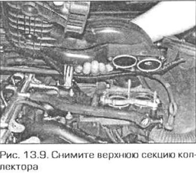
9. Loosen the nuts/bolts and remove the upper section of the manifold (Fig. 13.9).
10. Installation is carried out in the reverse order of removal, taking into account the following notes.
- a) Replace the upper section of the manifold seals.
- b) Route the hoses and wires in the same way as before disassembly.
- c) Connect and adjust the accelerator cable as described in paragraph 5.
Lower section of the intake manifold
Engine M43TU
11. Relieve pressure in the fuel system (see paragraph B).
12. Remove the upper section of the manifold as described above.
13. Drain the coolant.
14. Remove the injectors as described in paragraph 12.
15. Remove the bolt securing the oil dipstick tube bracket to the manifold.
16. Release the engine wiring harness from the lower section of the manifold.
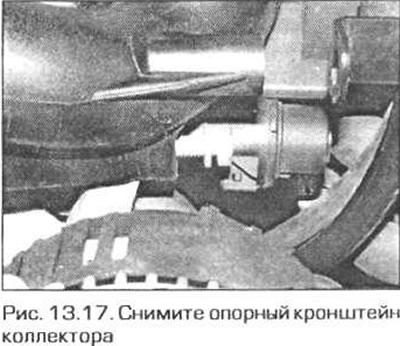
17. Remove the manifold support bracket mounting bolts (fig. 13.17).
18. Disconnect the remaining wires and hoses from the manifold and sensors. Mark them for proper installation.
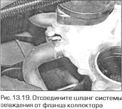
19. Disconnect the coolant hose from the manifold flange (fig. 13.19).
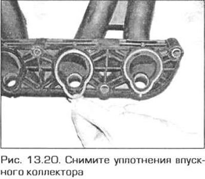
20. Loosen the nuts securing the lower section of the manifold to the cylinder head and remove the manifold (fig. 13.20).
21. Installation is carried out in the reverse order, taking into account the following notes.
- a) When installing the lower section of the manifold, replace the seals.
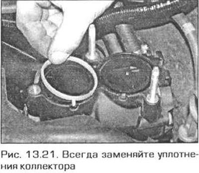
- b) When installing the upper section of the manifold, replace the seals (fig. 13.21).
- c) Route the wires and hoses as they were before disassembly. Connect the connectors in accordance with the marks made during disassembly.
- d) Install the injectors (see paragraph 12).
- d) Install the upper section of the manifold as described above in this paragraph.
- e) Finally, fill the fuel system (insert the fuel pump fuse and turn on the ignition). Before starting the engine, check for leaks.
Inlet connector
Engine N42
Note: Access to the underside of the manifold is limited.
22. Switch off the ignition. Remove the air cleaner as described in paragraph 12.
23. Remove the fuel rail and injectors (see paragraph 12).
24. In the left corner of the engine compartment, turn the fasteners 90° and remove the partition panel. Pull the hose and wires out of the panel together with the sealing bushings (see fig. 12.23).
25. Disconnect the electrical connectors on the throttle body and manifold. Release all wires and cables from the manifold fasteners. Disconnect the busbar from the dipstick guide tube.
26. On the underside of the manifold, loosen the clamp and disconnect the fuel tank ventilation hose from the manifold.
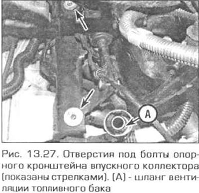
27. Under the manifold, unscrew the bolt securing the oil dipstick tube. Then unscrew the two screws securing the support bracket to the manifold (Fig. 13.27). The screws are easier to access from below, except for models with air conditioning, where access to the front screw is possible from above.
28. Under the starter, unscrew the bolt securing the cooling system tube bracket to the engine crankcase. This will allow you to move the tubes back, facilitating the removal of the manifold.
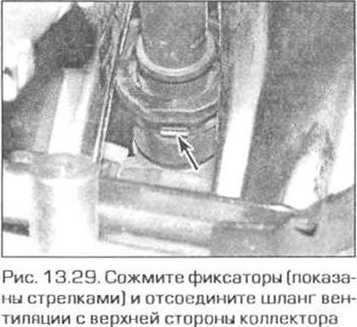
29. Disconnect the ventilation hose from the top of the manifold (fig. 13.29).
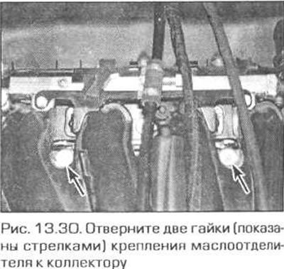
30. Unscrew the two nuts securing the oil separator to the lower side of the manifold (fig. 13.30).
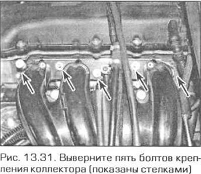
31. Remove the five manifold mounting bolts and remove the manifold from the cylinder head (fig. 13.31).
32. Check the condition of the manifold seals and, if necessary, replace them with new ones.
33. The manifold is installed in the reverse order, taking into account the following notes.
- a) Position the oil separator correctly with the guides facing the manifold.
- b) Tighten the manifold mounting bolts securely.
Engines M52TU and M54
34. To expand the working space, remove the air inlet duct for the interior heating and ventilation system from the rear of the engine compartment as follows.
- a) Turn the three latches of the cabin filter cover 90° counterclockwise and remove the cover. Pull out the filter.
- b) Unfasten the four fasteners of the box for laying the wires and remove the wiring from the box (see fig. 12.31).
- c) Unscrew the four screws securing the cabin filter housing and pull out the housing.
- d) Pull up the seal in the left corner of the engine compartment, turn the two fasteners counterclockwise and move the partition panel forward a little (see fig. 12.23).
- d) Remove the two screws and pull the air duct upwards (see fig. 12.24).
35. Remove the throttle body (paragraph 11) and a fuel rail with injectors (paragraph 12).
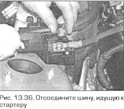
36. Open the jump start terminal on the right side of the engine compartment and disconnect the busbar going to the starter (fig. 13.36).
37. On the left side of the front side of the cylinder head, disconnect the electrical connector of the VANOS valve timing adjuster solenoid.
38 Disconnect the crankcase ventilation hose from the cylinder head cover.
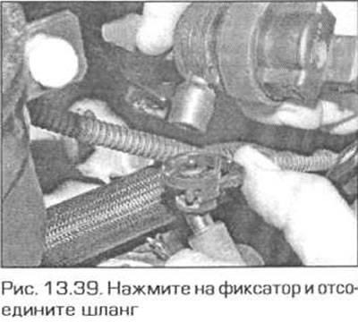
39. Press the retainer inward and disconnect the hose from the fuel tank ventilation valve (fig. 13.39)
40. Release the wires from the fastenings to the manifold and support bracket.
41. Disconnect the brake booster hose. To do this, cut the clamp and pull the plastic tube out of the hose.
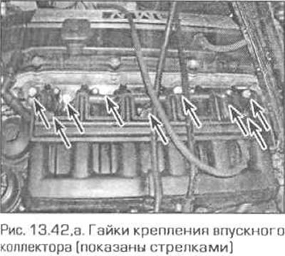
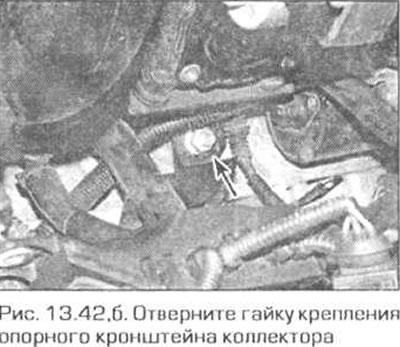
42. Unscrew the nine nuts securing the manifold to the cylinder head, as well as the nut of the support bracket under the manifold (fig. 13.42, a, b) Remove the manifold from the engine. On the M54 engine, disconnect the fuel pressure regulator vacuum hose. Remove the seals.
43. Check the condition of the seals and replace them with new ones if necessary.
44. The manifold is installed in the reverse order of removal.
Exhaust manifold
Engine M43TU
Note: Installation requires new manifold mounting nuts and a new gasket.
45. To improve access, raise the front of the vehicle and place it on reliable supports. Remove the crankcase guard from under the engine.
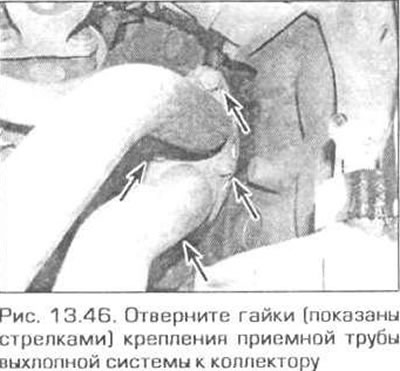
46. From under the car, unscrew the nuts securing the exhaust inlet pipe to the exhaust manifold (fig. 13.46).
47. Remove the bolts connecting the two halves of the exhaust system support to the gearbox bracket (see fig 14.4).
48. Loosen the bolt securing the support halves to the bracket, then remove the intake pipe from the exhaust manifold studs. Remove the gasket.
49. In the engine compartment, unscrew the manifold mounting nuts. Unscrew the nuts securing the secondary air injection system tube to the manifold (if any) and remove the tube.
50. Remove the manifold from the studs and remove it from the engine compartment. Remove the manifold gasket.
51. It is possible that when unscrewing the manifold nuts, some studs will come loose. These studs must be screwed back into place in the cylinder head before installing the manifold. To do this, screw two nuts onto the stud, pull them together, and screw the stud in by the top nut.
52. The manifold is installed in the reverse order. When installing, replace the gasket and nuts.
Engine N42
53. Raise the front of the car and place it on reliable supports. Remove the crankcase guard from under the engine.
54. Remove the eight bolts and the front strut between the lower suspension arms. The strut mounting bolts will need to be replaced when reinstalling.
55. Trace the oxygen sensor wiring and disconnect its electrical connector. If there are two sensors, mark the connectors so as not to mix them up during installation.
56. Loosen the bolts and nuts and disconnect the intake pipe from the manifold.
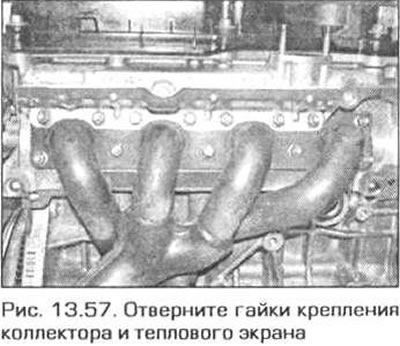
57. Unscrew the nuts securing the exhaust manifold with the screen and remove them from the cylinder head (fig. 13.57). The gasket can be thrown away. It is possible that when unscrewing the manifold nuts, some studs will come loose. These studs must be screwed back into place in the cylinder head before installing the manifold. To do this, screw two nuts onto the stud, pull them together, and screw the stud in by the top nut.
58. The manifold is installed in the reverse order. When installing, replace the gasket and nuts.
Engines M52TU and M54
59. To expand the working space, remove the air inlet duct for the heating and ventilation system from the rear of the engine compartment as follows.
- a) Turn the three latches of the cabin filter cover 90° counterclockwise and remove the cover. Pull out the filter.
- b) Unfasten the four fasteners of the box for laying the wires and remove the wiring from the box (see fig. 12.21).
- c) Unscrew the four screws securing the cabin filter housing and pull out the housing.
- d) Pull up the seal in the left corner of the engine compartment, turn the two fasteners counterclockwise and move the partition panel forward a little (see fig. 12.23).
- d) Remove the two screws and pull the air duct upwards (see fig. 12.24).
60. Raise the front of the car and place it on reliable supports. Remove the crankcase guard from under the engine.
61. Remove the eight bolts and the front strut between the lower suspension arms. The strut mounting bolts will need to be replaced when reinstalling.
62. Attach the lifting device straps to the engine lifting eye and pull the engine up to remove the weight from its mounts.
63. Remove the right engine mount with the support arm from under the vehicle.
64. Remove the plastic cover over the injectors. To do this, remove the two plugs and unscrew the screws underneath them.
65. Trace the oxygen sensor wiring and disconnect its electrical connector. If there are two sensors, mark the connectors so as not to mix them up during installation.
66. Loosen the bolts and nuts and disconnect the intake pipe from the manifold.
67. Raise the engine approximately 5 mm.
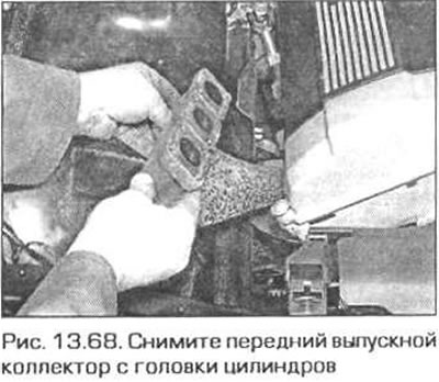
68. Loosen the front manifold mounting nuts and remove it from the engine (fig. 13.68). Be careful not to damage the manifold oxygen sensor.
69. Remove the rear manifold in the same way. Again, be careful not to damage the oxygen sensor
70. Installation of collectors is carried out in the reverse order, taking into account the following notes.
- a) Lubricate the manifold studs with graphite grease (or other composition that prevents the threaded connection from seizing)
- b) Replace the pads under the manifold and under the inlet pipe.
- c) Tighten the connector nuts to the specified torque.
This article is available at russian, bulgarian, belarusian, ukrainian, serbian, croatian, romanian, polish, slovak, hungarian
Article verified: Ilyinsky Matvey
Share information:
Previous articles
БМВ E46: Fuel and exhaust system
Next articles
Similar articles on other types of BMW cars:
Removal and installation the oil pan BMW 5 Series E12 (1972-1981)
Cylinder Head Cover — Removal and Installation BMW 7 Series E32 (1986-1994)
Pistons — removal and installation BMW X3 E83 (2003-2010)
Removal and installation the engine BMW X5 E53 (1999-2006)
Removal and installation the oil pan BMW 5 Series E12 (1972-1981)
Cylinder Head Cover — Removal and Installation BMW 7 Series E32 (1986-1994)
Pistons — removal and installation BMW X3 E83 (2003-2010)
Removal and installation the engine BMW X5 E53 (1999-2006)
Link in different formats to this page
Visitor comments
No comments yet
- General information
- Manual
- Maintenance
- Power unit
- Engine repair
- Cooling system
- Power system (gasoline)
- Injection system (gasoline)
- Fuel system (diesel)
- Exhaust system
- Ignition system
- Charge and launch systems
- Transmission
- Car gearbox
- Clutch and drive shafts
- Chassis
- Brake system
- Suspension front and rear
- Steering
- Body
- Body care and repair
- Exterior
- Interior
- Electrical equipment
- Troubleshooting
- Lighting and signaling
- Equipment and devices
- Heater and air conditioner
- Electrical circuits
- General information
- Manual
- Repair on the road
- Weekly checks
- Maintenance
- Troubleshooting
- Power unit
- 4 cylinder engines
- 6 cylinder engines
- Engine overhaul
- Cooling and heating
- Fuel and exhaust system
- Starting and charging system
- Ignition system
- Transmission
- Clutch
- Mechanical gearbox
- Automatic gearbox
- Cardan and drive shafts
- Chassis
- Brake system
- Wheel suspension
- Steering
- Body
- Exterior
- Interior
- Electrical equipment
- Equipment and devices
- Electrical circuits
- General information
- Maintenance
- Power unit
- Engine repair
- Cooling system
- Ignition system
- Supply system
- Fuel injection system
- Exhaust system
- Transmission
- Clutch
- Car gearbox
- Front and rear axle
- Chassis
- Steering
- Brake system
- Body
- Exterior
- Interior
- Electrical equipment
- Heating system
- Equipment and devices
- Power devices
- Electrical circuits
- Power unit
- M10/M20 engine
- M40 engine
- Ignition system
- Lubrication system
- Cooling system
- Supply system
- Fuel injection
- Exhaust system
- Transmission
- Clutch
- Manual gearbox
- Front axle
- Rear axle
- Chassis
- Steering
- Brake system
- Body
- Exterior
- Interior
- Electrical equipment
- Heating system
- Equipment and devices
- Electrical circuits
- General information
- Specifications
- Operation and maintenance
- 4-cylinder engine
- Engine repair
- Cooling and lubrication system
- Supply system
- Ignition system
- 6-cylinder engine
- Engine repair
- Cooling and lubrication system
- Supply system
- Fuel injection system
- Ignition system
- Transmission
- Clutch
- 4-speed manual gearbox
- 5-speed manual gearbox
- Automatic gearbox
- Cardan and rear axle
- Chassis
- Steering
- Front suspension
- Rear suspension
- Brake system
- Electrical equipment
- Equipment and devices
- Electrical circuits