
Table of contents: General description ↓ Examination ↓
- Home
- BMW 5 Series
- E28
- Power unit
- Control system
- Evaporative emission control system (EVAP)
Evaporative emission control system (EVAP) (BMW 5 Series E28)
General description
EVAP system diagram on M10 engine (the rest are similar)
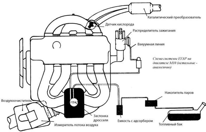
This system is typically installed on vehicles equipped with a catalytic converter.
When the engine is turned off, the fuel in the fuel tank evaporates, creating vapor pressure. The gasoline vapor recovery system collects these vapors in a container with an adsorber. When driving, the vapor removal valve opens slightly and fuel vapors gradually enter the intake manifold and burn. When starting a cold engine or idling, the vapor removal valve does not allow vapors to enter the intake manifold and enrich the fuel mixture excessively.
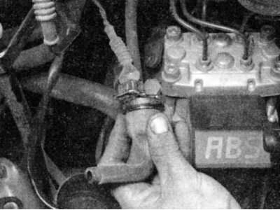
There are two types of vapor purge valves: electrically operated and vacuum operated. To determine which valve is installed on your vehicle, follow the hose from the canister until you find the valve. Some valves are installed on the intake manifold, while others are installed near the canister. See if the valve has an electrical connector or a vacuum line running to it.
A faulty EVAP system will only affect engine performance when the engine is warm. The EVAP system is not usually the cause of hard cold starts or other cold engine problems.
Examination
Vacuum operated vapor vent valve
1. Disconnect the vacuum line from the valve and blow into the larger port on the valve. The valve should be closed and air should pass through.
On some models, a thermal vacuum valve is installed, which prevents the removal of vapors until the temperature of the cooler reaches approximately 46°C. Check this valve to make sure that it operates under the influence of discharge at the correct temperature. The valve is usually located in the inlet pipe near the temperature switch and the cooler temperature sensor.
2. Disconnect the thin vacuum hose from the vapor release valve and use a hand vacuum pump to create a vacuum at the valve inlet. The valve should open and begin to let air through.
3. If the test is negative, replace the valve.
Electrically controlled vapor vent valve
1. Disconnect all lines from the valve (except for the electrical connector) and move it to a convenient place for testing.
2. Check that the valve clicks when the ignition is turned on.
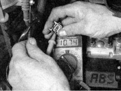
3. If the valve does not click, disconnect the connector from the valve and check the power supply with a test lamp or voltmeter.
4. If battery voltage is present but the valve does not work, replace it. If voltage is not present, check the Motronic control unit and wires.
Capacity with adsorber
1. Mark the location of all hoses, then disconnect them from the container.
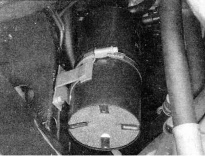
2. Slide the container out of the mounting clamp. On some models, you may need to loosen the clamp.
3. Visually inspect the container for leaks and damage.
4. If leaks or damage are detected, replace the container.
This article is available at russian, bulgarian, belarusian, ukrainian, serbian, croatian, romanian, polish, slovak, hungarian
Article verified: Zhuravleva Isolda
Share information:
Previous articles
БМВ E28: Control system
Next articles
Similar articles on other types of BMW cars:
Technical data of the emission control system BMW 3 Series E46 (1998-2006, petrol)
Speed control system (tempostat) BMW 3 Series E46 (1998-2006)
AT control system (2000) BMW 7 Series E38 (1994-2001)
Checking the cooling system for tightness BMW 7 Series E32 (1986-1994)
Cruise control system (optional) BMW X3 E83 (2003-2010)
Electrical diagram of the knock control system BMW X5 E53 (1999-2006)
Link in different formats to this page
Visitor comments
No comments yet
- General information
- Governing bodies
- Manual
- Maintenance
- Power unit
- Engine repair
- Lubrication system
- Cooling system
- Ignition system
- Supply system
- Injection system (gasoline)
- Injection system (diesel)
- Exhaust system
- Transmission
- Clutch
- Car gearbox
- Front axle
- Rear axle
- Chassis
- Steering
- Brake system
- Wheels and tires
- Body
- Interior
- Exterior
- Heating system
- Electrical equipment
- Equipment and devices
- Power devices
- Windscreen wipers
- Electrical circuits
- General information
- Manual
- Maintenance
- Power unit
- Engine repair
- Ignition system
- Engine lubrication system
- Cooling system
- Fuel system (gasoline)
- Fuel system (diesel)
- Exhaust system
- Transmission
- Clutch
- Car gearbox
- Chassis
- Front and rear suspension
- Steering
- Brake system
- Body
- Exterior
- Interior
- Electrical equipment
- Heating system
- Equipment and devices
- Power devices
- Electrical circuits
- General information
- Manual
- Maintenance
- Power unit
- Engine in a car
- Engine overhaul
- Cooling system
- Supply system
- Ignition system
- Control system
- Transmission
- Clutch
- Manual gearbox
- Automatic gearbox
- Transmission line
- Chassis
- Steering
- Front suspension
- Rear suspension
- Brake system
- Body
- Body elements
- Car care and painting
- Electrical equipment
- Heater and air conditioner
- Equipment and devices
- Starter and generator
- Electrical circuits
- General information
- Operation and maintenance
- Specifications
- Power unit
- Engine repair
- Cooling and lubrication system
- Supply system
- Ecotronic power supply system
- Fuel injection system
- Ignition system
- Transmission
- Clutch
- Gearbox BMW 242/4
- Gearbox Getrag 262/8
- Gearbox Getrag 265/6
- Automatic gearbox
- Cardan gear
- Rear axle
- Chassis
- Steering
- Front suspension
- Rear suspension
- Brake system
- Electrical equipment
- Equipment and devices
- Electrical circuits