
- Home
- BMW 5 Series
- E28
- Power unit
- Control system
- Information sensors
Information sensors (BMW 5 Series E28)
For additional information on the location and diagnostics of the information sensors described in this Section, refer to Chapters Power supply system and Ignition system.
Coolant temperature sensor
General description
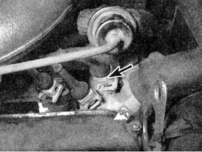
Coolant temperature sensor (shown by arrow) usually located near the temperature gauge, near the fuel pressure regulator and is a thermistor (a resistor whose resistance changes with temperature). The change in resistance determines the voltage drop on the sensor. At low temperatures, the sensor resistance is high. As the temperature rises, the resistance drops. Failures in the sensor circuit in most cases occur due to loosening of the wire contact or its short circuit; if there are no problems with the wires, check the sensor as described below.
Examination
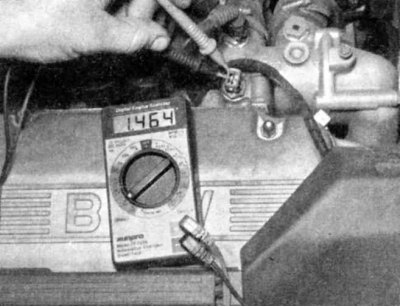
1. When checking the sensor, first measure its resistance in a cold state (typically 2100 to 2900 ohms).
2. Next, start the engine and warm it up to normal operating temperature. The resistance should be lower (typically 270 to 400 ohms).
If restricted access to the temperature sensor makes it difficult to connect electrical probes to its contacts, remove the sensor as described below and test it in a container of heated water simulating operating conditions.
Wait until the engine has cooled down completely before starting this procedure.
Replacement
1. To remove the sensor, press the spring lock, disconnect the electrical connector, then carefully unscrew the sensor. Be prepared for a small amount of coolant to leak out; to reduce leakage, prepare a new sensor and install it as soon as possible.
Handle the coolant sensor with extreme care. Damage to this sensor will affect the operation of the entire fuel injection system.
Before removing the sensor, it may be necessary to drain a small amount of coolant from the radiator.
2. Before installing the sensor, make sure its threads are clean and apply a small amount of compound to them.
3. Installation is the reverse of removal.
Oxygen concentration sensor
General description
Oxygen sensors are typically found on vehicles with a catalytic converter. Most oxygen sensors are located in the exhaust pipe behind the exhaust manifold. On the 535, the oxygen sensor is located in the catalytic converter. The sensor's electrical connector faces the dash for easy access (left side).
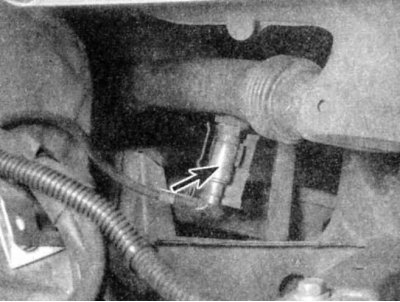
Oxygen sensor (shown by arrow) typically located in the exhaust pipe behind the exhaust manifold, it monitors the oxygen concentration in the exhaust gases.
Oxygen in the exhaust gas interacts with the oxygen sensor and creates a voltage that varies from 0.1 V (high oxygen concentration, lean mixture) up to 0.9 V (low oxygen concentration, rich mixture). The ECU constantly monitors this voltage change to determine the oxygen-fuel ratio in the mixture. The ECU controls the pulse width of the fuel injectors (opening time) changes the air/fuel ratio. A fuel mixture of 14.7 parts air to 1 part fuel is the ideal mixture for minimizing exhaust emissions while allowing the catalytic converter to operate at its most efficient. This 14.7 to 1 ratio is what the ECU and oxygen sensor are trying to maintain at all times.
The oxygen sensor does not produce any voltage if its temperature is below the normal operating temperature of about 320°C. During this initial warm-up period, the ECU operates in "open loop" mode (that is, without information from the sensor).
When the engine warms up to normal operating temperature and/or has been running for two minutes or more and if the oxygen sensor produces a constant voltage below 0.45 V at 1500 RPM or higher, the ECU fault code memory is activated.
If a problem occurs with the oxygen sensor or its circuit, the ECU operates in "open loop" mode, meaning it controls fuel delivery according to the programmed fault code value instead of the oxygen sensor information.
Proper operation of the oxygen sensor depends on four conditions:
1. Electrical - The low voltage produced by the sensor depends on good, clean contacts, which should be checked whenever the sensor is suspected or detected to be malfunctioning.
2. Outside Air Intakes - The sensor is designed to allow air to enter the inside of the sensor. Whenever you remove the sensor, make sure that the air passages are not blocked.
3. Correct operating temperature - The ECU does not respond to temperature sensor signals until it has warmed up to approximately 320°C. This factor must be taken into account when assessing the sensor's performance.
4. Unleaded Fuel - Using unleaded fuel is essential for the sensor to function properly. Make sure you are using this type of fuel.
In addition to the above conditions, special attention should be paid to the maintenance of the sensor.
- The oxygen sensor is equipped with a cable with an electrical connector that must not be disconnected from the sensor. Damage or disconnection of the cable or connector will adversely affect the operation of the sensor.
- Grease, dirt or other foreign matter must not be allowed on the electrical connector or on the perforated end of the sensor.
- Do not use cleaning solvents of any type on the sensor.
- Do not drop the sensor and handle it with care.
- The silicone case must be installed correctly to prevent it from melting and to ensure the sensor works properly.
Examination
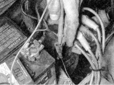
1. Warm up the engine and let it idle. Disconnect the electrical connector from the oxygen sensor and connect the positive probe of the voltmeter to the output terminal of the sensor (refer to the following table), and the negative probe to the body. The oxygen sensor, when heated (up to 320°C), produces a very small voltage signal. Typically, the signal voltage is in the range of 0.1 to 1.0 V).
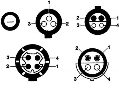
Cable-side oxygen sensor connector options. Use the appropriate sensor terminals for the test procedures (there are three different four-wire oxygen sensor connectors - don't mix them up).
Most oxygen sensor electrical connectors are located at the rear of the engine near the dash. Look for a large rubber boot with a thick cable. On early 535i models, the oxygen sensor heater circuit connector is located under the vehicle. Look for a small protective cover. These models should have their own oxygen sensor so access is similar to other models. Consult your dealer for more information.
2. While monitoring the voltage, increase and then decrease the engine speed.
3. When the speed increases, the voltage should increase to 0.5 - 1.0 V. When the speed decreases, the voltage should decrease to 0 - 0.4 V.
4. If applied, inspect the oxygen sensor heater (models with multi-wire sensors). With the ignition on, disconnect the oxygen sensor electrical connector and connect it to the terminals indicated in the table (see below), voltmeter. There should be battery voltage between the contacts (approximately 12V).
5. If the readings are incorrect, check the oxygen sensor heater relay (see chapter On-board electrical equipment system). If relay information is not available, refer to the vehicle owner's manual to determine the exact location of the oxygen sensor heater relay. The relay should receive battery voltage.
6. If the oxygen sensor fails any of these tests, replace the sensor.
Replacement
Because the sensor is mounted in the exhaust manifold, converter or pipe, which all contract when cooled, the oxygen sensor can be very difficult to remove when the engine is cold. Rather than risk damaging the sensor (if you plan to use it again in another manifold or pipe), start the engine and let it run for a minute or two, then turn it off. Be careful not to burn yourself when performing the following procedure.
1. Disconnect the negative battery cable.
If your vehicle's radio is equipped with an anti-theft system, make sure you know the correct activation code before disconnecting the battery. Refer to Section 1 for information before disconnecting the wire Anti-theft audio system and instrument cluster language.
If a message in another language appears on the instrument cluster display after connecting the battery, refer to Section 1 for the language setting procedure Anti-theft audio system and instrument cluster language.
2. Raise the vehicle and place it on stands.
3. Disconnect the electrical connector from the sensor.
4. Carefully unscrew the sensor.
Excessive force may damage the threads.
5. To facilitate subsequent removal, high-temperature anti-corrosion compound should be applied to the sensor thread. The thread of the new sensor is already covered with such a compound, but if the old sensor is removed and installed, apply compound to the thread.
6. Install the sensor and tighten it firmly.
7. Connect the sensor cable electrical connector to the main engine cable.
8. Lower the vehicle and connect the battery.
| Oxygen sensor type | Sensor output signal | Heater power supply (12V) |
| Not heated (single-wire) | black wire () | absent |
| Heated (three-wire) | contact 1 () | contacts 3 () and 2 (-) |
| Heated (four-wire) | contact 2 () | contacts 4 () and 3 (-) |
Throttle Position Sensor (TPS)
General description
The throttle position sensor (TPS) is located at the end of the throttle shaft in the throttle body. By monitoring the TPS output voltage, the ECU can determine fuel delivery based on knowledge of the throttle valve angle (specified by the driver). In this system, the TPS operates more like a switch than a potentiometer. One set of contacts on the throttle valve switch is closed (connection of contacts) only at idle. The second set of contacts closes when the throttle is fully open. Between these positions, both sets of contacts are open (no connection). A bad or weakened TPS can cause erratic fuel injection and unstable idle speed because the ECU thinks the throttle is moving.
All models (except early 535i models with automatic transmission) have a combined idle and full throttle switch; a separate idle switch indicates the closed throttle position, while the TPS is used to indicate wide open throttle. On 535i models with automatic transmission, the TPS is connected directly to the automatic transmission control unit. At wide open throttle, the transmission control unit sends a signal of open throttle to the Motronic control unit.
All models except early 535i with automatic transmission
Examination
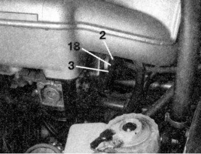
The L-Jetronic system TPS is located under the intake manifold (contacts shown).
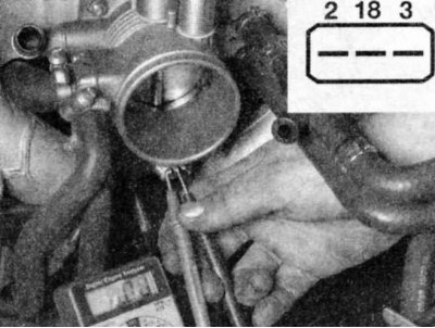
1. Disconnect the electrical connector from the TPS and connect an ohmmeter to pins 2 and 18. Check for a short between pins 2 and 18 with the throttle closed (shown is a late Motronic system).
2. Slightly open the throttle with your hand. Slowly release the throttle so that 0.2-0.6 mm remains before the stop. The ohmmeter should show a short circuit.
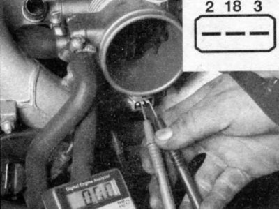
3. Check the resistance between pins 3 and 18 with the throttle open. There should be a short within 8-12 degrees of the fully open position. If the reading is incorrect, adjust the TPS.
4. If all resistance readings are correct and the TPS is adjusted correctly, check the sensor power supply (5V) and, if necessary, inspect the wiring between the sensor and the ECU (see chapter On-board electrical equipment system).
Adjustment
1. If the adjustment is not as required (item 1-2), loosen the TPS screws and rotate the sensor to the correct position. Follow the TPS inspection procedure above and tighten the screws after completing the adjustment.
2. Check TPS again; if the readings are correct, reconnect the TPS cable connector.
Early 535i models with automatic transmission
Examination
1. First check the TPS short circuit. To check the short circuit, follow the procedures in steps 1-2.
2. Next, check the idle speed switch. Disconnect the idle speed switch cable connector and connect an ohmmeter to contacts 1 and 2. There should be a short circuit. Slightly open the throttle and measure the resistance. There should be no short circuit.
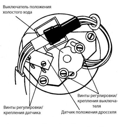
Idle Position Switch and TPS on early 535i models with automatic transmission.
3. Check for correct TPS output voltage signals with the throttle closed and the ignition on. Connect the voltmeter probe to pin 3 (black wire) from the back of the TPS connector and check the voltage relative to the chassis. It should be 5 V. Also, check the voltage between pin 3 (black wire) and contact 1 (brown wire). There should be 5V here too.
4. Check the voltage between pin 2 (yellow wire) and contact 1 (brown wire) and slowly open the throttle. The voltage should increase steadily from 0.7 V (throttle closed) up to 4.8 V (throttle fully open).
Adjustment
1. First, measure the stabilized voltage. With the ignition on and the throttle fully closed, measure the voltage between pin 3 (black wire) and contact 1 (brown wire). It should be around 5V.
2. Next, loosen the sensor mounting screws and connect between contact 2 (yellow wire) and contact 3 (black wire) voltmeter. With the throttle fully open, rotate the switch until the voltage becomes 0.20 - 0.24 V less than the stabilized voltage.
To measure such small voltage changes, you will need a digital voltmeter.
3. Check TPS again; if the readings are correct, connect the electrical connector to the TPS. It is advisable to lock the TPS screws with paint or thread locking compound.
Air flow meter
General description
The air flow meter is located in the intake air duct. The air flow meter measures the amount of air entering the engine. The ECU uses this information to control fuel delivery. A large amount of air means acceleration, while a small amount of air means deceleration or idling. For all diagnostic tests and replacement procedures for the air flow meter, refer to Chapter Power supply system.
Ignition Timing Sensors
The ignition timing in Motronic systems is controlled electronically and is not adjustable. At start-up, the crankshaft position sensor sends a signal to the ECU, which determines the starting point of the ignition timing. When the engine is running, the ignition timing is continuously changed depending on various input signals to the ECU. The engine speed is determined by the speed sensor. In early Motronic systems, the reference sensor and the speed sensor are mounted above the flywheel on the clutch housing. In later Motronic systems, there is a single sensor (pulse sensor), mounted above the crankshaft pulley. This sensor functions as both a speed sensor and a position sensor. For more information, see Chapter Ignition system.
Some models are equipped with a TDC sensor at the front of the engine. This sensor is part of the BMW Service Test Unit and is not part of the Motronic ignition system.
This article is available at russian, bulgarian, belarusian, ukrainian, serbian, croatian, romanian, polish, slovak, hungarian
Article verified: Zhuravleva Isolda
Share information:
Previous articles
БМВ E28: Control system
Next articles
Similar articles on other types of BMW cars:
General information about engines BMW 3 Series E30 (1982-1994)
Gearbox. General information BMW 3 Series E36 (1990-2000)
Engine Overhaul. General Information BMW 7 Series E32 (1986-1994)
General information about security system elements BMW 7 Series E38 (1994-2001)
Technical information of the car BMW X3 E83 (2003-2010)
General information about M54 engines BMW X5 E53 (1999-2006)
Link in different formats to this page
Visitor comments
No comments yet
- General information
- Governing bodies
- Manual
- Maintenance
- Power unit
- Engine repair
- Lubrication system
- Cooling system
- Ignition system
- Supply system
- Injection system (gasoline)
- Injection system (diesel)
- Exhaust system
- Transmission
- Clutch
- Car gearbox
- Front axle
- Rear axle
- Chassis
- Steering
- Brake system
- Wheels and tires
- Body
- Interior
- Exterior
- Heating system
- Electrical equipment
- Equipment and devices
- Power devices
- Windscreen wipers
- Electrical circuits
- General information
- Manual
- Maintenance
- Power unit
- Engine repair
- Ignition system
- Engine lubrication system
- Cooling system
- Fuel system (gasoline)
- Fuel system (diesel)
- Exhaust system
- Transmission
- Clutch
- Car gearbox
- Chassis
- Front and rear suspension
- Steering
- Brake system
- Body
- Exterior
- Interior
- Electrical equipment
- Heating system
- Equipment and devices
- Power devices
- Electrical circuits
- General information
- Manual
- Maintenance
- Power unit
- Engine in a car
- Engine overhaul
- Cooling system
- Supply system
- Ignition system
- Control system
- Transmission
- Clutch
- Manual gearbox
- Automatic gearbox
- Transmission line
- Chassis
- Steering
- Front suspension
- Rear suspension
- Brake system
- Body
- Body elements
- Car care and painting
- Electrical equipment
- Heater and air conditioner
- Equipment and devices
- Starter and generator
- Electrical circuits
- General information
- Operation and maintenance
- Specifications
- Power unit
- Engine repair
- Cooling and lubrication system
- Supply system
- Ecotronic power supply system
- Fuel injection system
- Ignition system
- Transmission
- Clutch
- Gearbox BMW 242/4
- Gearbox Getrag 262/8
- Gearbox Getrag 265/6
- Automatic gearbox
- Cardan gear
- Rear axle
- Chassis
- Steering
- Front suspension
- Rear suspension
- Brake system
- Electrical equipment
- Equipment and devices
- Electrical circuits