
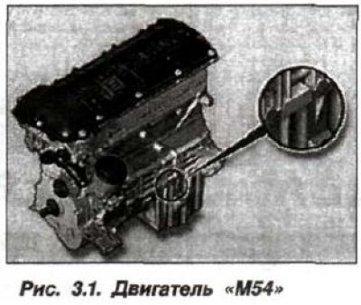
The engine block and its head are made of a light alloy based on aluminum. The cylinder block has dry thin-walled cast iron liners inserted during the manufacturing process (pouring) of the block. The cylinder head has 4 valves, which are located at an angle of 39.5°. The cooling system is closed, liquid, forced. The lubrication system is combined - under pressure and splashing. The fuel system is injector (injection), with electronic control. The crankshaft is seven-support and rotates in plain bearings.
The engine uses an overhead valve timing mechanism with two camshafts located in the cylinder head (dOHC system) and hydraulic cylindrical tappets. The exhaust camshaft is driven by the engine crankshaft sprocket. The exhaust and intake camshafts are connected by a chain. The engine has an adjustable valve timing drive, which automatically changes the opening and closing of the intake and exhaust valves by changing the initial position of the camshafts. This system has a brand name - "Doppe/-VANOS" (Doppel Variable Nockenwe Hensteuerung), abbreviated as "D-VANOS".
The change in the position of the intake and exhaust shafts is carried out by signals from the ECU-KSUD, by opening and closing the oil pressure supply valve in the system's adjustment mechanism. A special feature of the engine is the adjustable resonant boost system by changing the length of the air intake channels. Thanks to hydraulic tappets (hydraulic pushers), there is no need to adjust valve clearances during operation.
The supply of oil under pressure to the engine is provided by a mechanical oil pump with internal gears. The oil pump has a chain drive from the crankshaft and is located in the oil pan of the crankcase. Oil is taken from the oil pan by the pump receiver and is supplied through channels and pipelines to the bearings of the crankshaft and camshafts, hydraulic tappets, and also to the working surfaces of the cylinders from the located injectors.
The centrifugal type liquid cooling system pump is mounted on the front wall of the engine cylinder block. It is driven by a V-belt from the engine crankshaft pulley. The same belt is used as a drive for the generator and the power steering pump. A viscous coupling is installed on the pump shaft, which ensures that the fan is turned on depending on the coolant temperature. The cooling system is sealed and must be constantly filled with antifreeze.
The electronic engine control system ensures the preparation of the fuel-air mixture and its ignition, as well as a number of other control functions. The M54 engines use a modification of the fuel injection and ignition system model "MS.45" from Siemens (Germany), which has the indexation DME ("Digital Motor-Elektronik" — Motronic — digital electronic engine management system). Hereinafter it will be called briefly — "DME" or "Motronic" (Fig. 3.2). The ignition system is fully electronic with individual ignition coils and is controlled by a single ECU-KSUD from the DME.
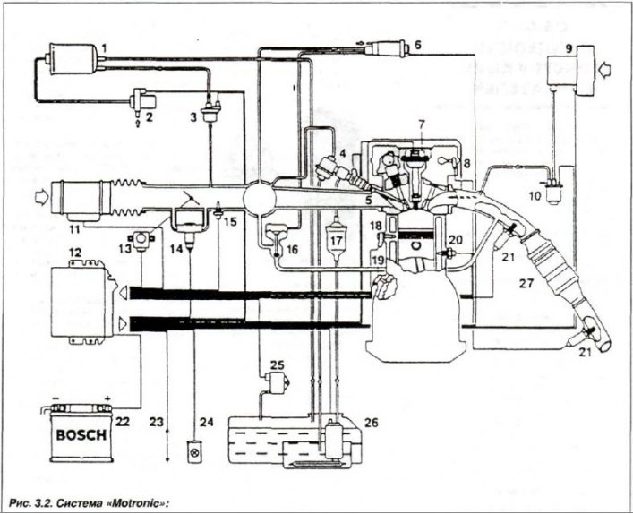
1 - tank with activated corners; 2 - air inlet valve; 3 - purge valve; 4 - fuel pressure regulator; 5 - nozzle; 6 - pressure regulator; 7 - ignition coil; 8 - camshaft sensor; 9 - additional air pump; 10 - air lock; 11 - IRV; 12 - ECU; 13 - throttle position sensor; 14 - idle valve; 15 - air temperature sensor; 16 - EGR valve; 17 - fuel filter; 18 - knock sensor; 19 - engine shaft speed sensor; 20—engine temperature sensor; 21 - oxygen content sensor in OR, 22 - AB; 23 - LUC diagnostics; 24 - SBP indicator; 25 - differential pressure sensor; 26 - Electric fuel pump; 27 - Neutralizer
Gasoline engines use fuel with an octane rating of ROZ-95, but the ability to suppress detonation in individual cylinders allows the use of fuels with octane ratings from ROZ-91 to ROZ-98. In the first case, fuel consumption increases due to loss of power, while in the second case, there is fuel savings and increased power. The transmission is all-wheel drive (4x4), with manual or automatic gearbox control, mounted on the rear wall (end) of the engine and is made in the all-wheel drive version.
Table 3.1 Technical characteristics of the engine model "M54"
| Start of engine production | january 1999 | ||
| Model index | M54B22 | M54B25 | M54B30 |
| Cylinder arrangement | Row, 6 | ||
| Cylinder diameter, mm | 80.0 | 84.0 | 84,0 |
| Piston stroke, mm | 72,0 | 75,0 | 89,6 |
| Working volume, cm³ | 2171 | 2494 | 2979 |
| Compression ratio | 10,8 | 10,5 | 10,2 |
| Compression pressure, kg/cm² | 10—11 | ||
| Nominal power, | |||
according to EEC standard, kW | 125 | 141 | 170 |
according to DIN standard, hp. | 170 | 192 | 231 |
| Rotation speed, min⁻¹ | 6100 | 6000 | 5900 |
| Maximum torque | |||
according to EEC standard, N·m | 210 | 245 | 300 |
according to DIN standard, kgf.m. | 21,4 | 25,0 | 30,6 |
| Rotation speed, min*¹ | 3500 | 3500 | 3500 |
| Maximum frequency, min*¹ | 6500 | ||
| Model of mixture formation | MS 45 by Siemens | ||
| Cylinder firing order | 1 — 5 — 3 — 6 — 2 — 4 | ||