
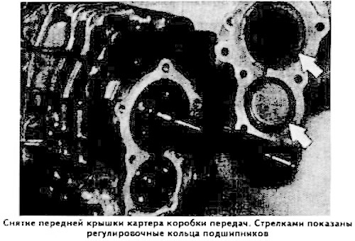
Secure the gearbox on stand 23.0.160 and drain the oil from it. Remove the front cover of the gearbox housing, being careful not to damage the adjusting rings (shown by arrows in the photo).
Remove the retaining ring, thrust washer and adjusting ring from the end of the input shaft.
Press the rear ball bearing of the primary shaft out of the crankcase seat using puller 23.2.020, being careful not to damage the spacer sleeve.
Press the front ball bearing of the intermediate shaft out of the crankcase socket using puller 23.2.050.
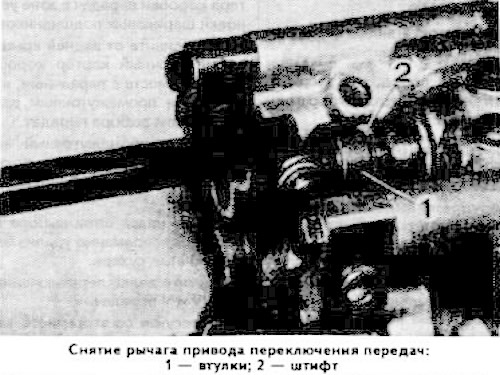
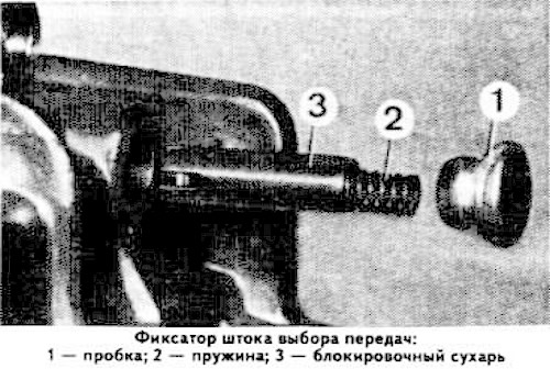
Unscrew plug 1 (see photo) of the gear selection rod retainer, remove spring 2 and locking cracker 3.
Unscrew the reverse light switch, being careful not to damage the gasket.
Remove the front part of the rear cover of the transmission case.
Remove the primary and secondary shafts.
Disassemble the secondary shaft.
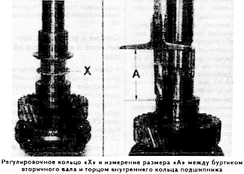
Determine the thickness of the adjustment ring "X" (see photo) as follows:
Place on secondary shaft:
- 3rd gear pinion with needle bearing, 3rd gear synchronizer locking ring, sliding clutch and synchronizer locking ring;
- 2nd gear with needle bearing, sleeve with shoulder and inner bearing ring, preheating the ring to a temperature of about 80°C.
Determine the distance "A" (see photo) between the flange of the secondary shaft and the end face of the inner bearing ring.
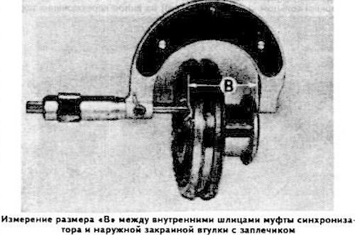
Determine the distance "B" (see photo) between the internal splines of the synchronizer sliding sleeve and the outer edge of the sleeve with the shoulder.
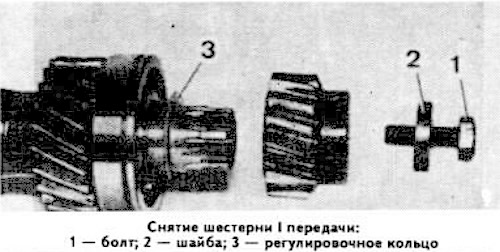
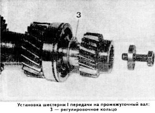
Unscrew bolt 1 (see photo), remove washer 2, remove the 1st gear pinion using two screwdrivers, being careful not to damage adjusting ring 3.
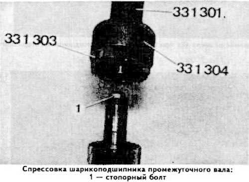
Press the ball bearing off the intermediate shaft using puller 33.1.301, removable cups 33.1.303 and ring 33.1.304.
Warning: To avoid damaging the threads of bolt 1 (see photo), tighten it fully.
Press a new bearing onto the intermediate shaft.
Measure the distance "C" between the end of the intermediate shaft and the end of the ball bearing.
Measure the height "D" of the 1st gear of the intermediate shaft.
The difference between dimensions "C" and "D" determines the thickness of the adjusting ring 3.
Install the selected adjusting ring in front of the 1st gear.
Heat the 1st gear pinion to about 80°C and press it onto the intermediate shaft. Screw the bolt into the end of the shaft, applying a glue such as Loctite "Frenbloc" to its thread.
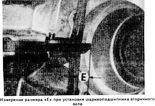
Install the secondary shaft ball bearing between the crankcase and the support ring.
Measure the depth "E" of the crankcase seat, which should be 13.1 mm.
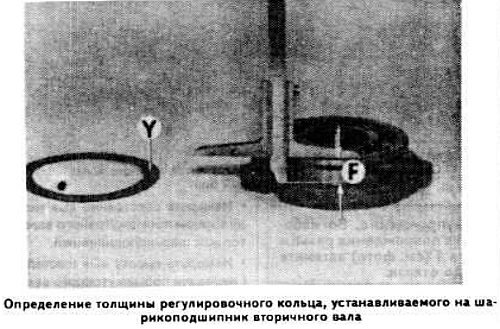
Insert the ball bearing into the support ring.
Measure the distance "F" between the outer end of the bearing and the support ring.
The difference between the dimensions "E" and "F" determines the thickness "Y" of the installed adjustment ring.
(The original article is available on the website «bmwman.ru»)