



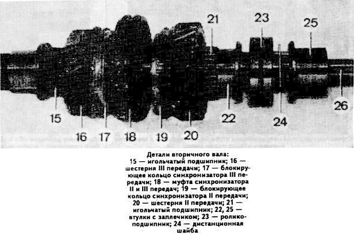
Check the condition of roller bearing 23 and replace it if necessary.
Heat the intermediate housing in the ball bearing pressing area to approximately 80°C and install the secondary and intermediate shafts simultaneously.
Install locks on both sides of the secondary shaft.
Press gear 2, 1st gear, synchronizer locking ring 3, needle bearing 4, synchronizer sliding sleeve 5, 1st gear and reverse gear engagement fork with rod 6 onto the secondary shaft, place cam 7 on the fork rod and secure it with a pin.
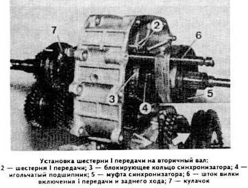
Install the split thrust ring of the 1st gear into the groove of the secondary shaft.
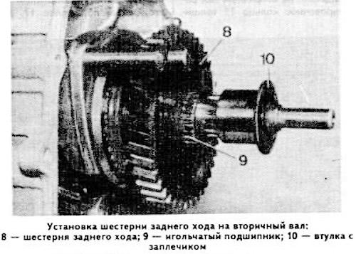
Press the reverse gear 8, needle bearing 9 and sleeve with shoulder 10 onto the secondary shaft. To facilitate installation, heat the sleeve to approximately 80°C.
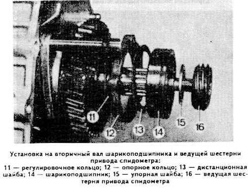
Place the adjusting ring 11 with a thickness of 0.5 mm, the support ring 12, the spacer washer 13, the ball bearing 14, the thrust washer 15 and the speedometer drive pinion 16 on the secondary shaft. To facilitate installation, heat the inner ring of the bearing and the speedometer drive pinion to a temperature of about 80°C.
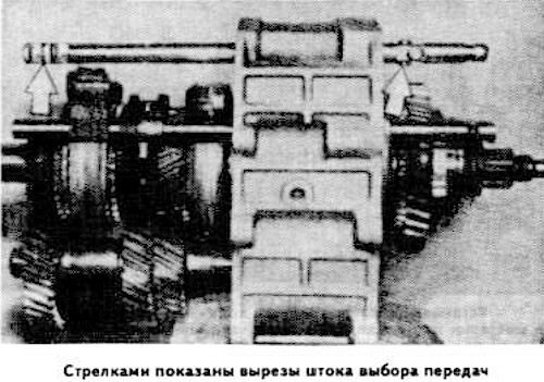
Install the shift forks of the II and III, IV and V gears. The shift fork of the IV and V gears has the greatest length. Insert the gear selection rod, putting the locking crackers in place. Install the gear selection rod so that its cutouts are facing downwards.
Remove three plugs.
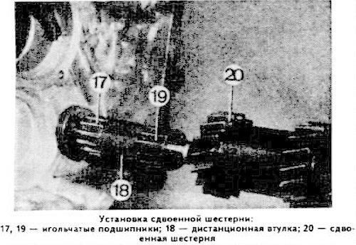
Install needle bearing 17, spacer sleeve 18, needle bearing 19 and double gear 20 on the secondary shaft.
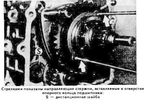
Screw the two guide rods into the bearing support ring. The cutout of the support ring should be facing downwards. Lock the spacer washer "S" (see photo).
Heat the rear cover of the gearbox housing to a temperature of approximately 80°C in the area where the ball bearings are pressed in.
Apply grease to the intermediate gearbox housing gasket.
Install the intermediate crankcase with shafts on the rear cover.
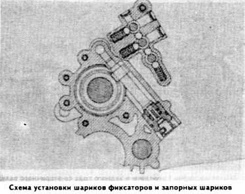
Insert the locking balls and the locking balls of the 1st gear and reverse gear fork rod into the sockets (see picture).
Place the intermediate case onto the guide rods until it stops and tighten the bolts securing it to the rear cover.
Tighten the secondary shaft rear bearing support ring mounting bolts and remove the guide rods.
Insert the 2nd and 3rd gear shift fork rod into the support spring until it stops. Replace the locking balls and the locking balls. Move the fork rod until it stops and lock the fork with the pin.
Before installing the rod 2 (see photo) of the shift fork for the IV and V gears, put the lever 3 on the gear selection rod.
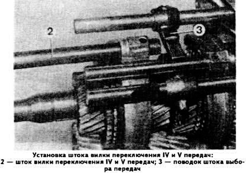
Insert the IV and V gear shift fork rod into the support spring until it stops. Put the locking balls and the locking balls in place. Push the rod until it stops. Insert the pins into the IV and V gear shift fork and gear selection rod carrier holes.
Install the plugs, lubricating them with sealant.
Install the secondary shaft flange of the gearbox and tighten its mounting nut, having previously applied glue like Loctite "Frenbloc" to the thread. Bend the tab of the lock washer into the flange cutout. Install the gearbox housing.
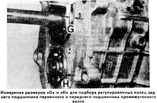
Adjust the position of the primary and intermediate shaft ball bearings relative to the front cover of the gearbox housing. Measure the protrusion of the bearings relative to the plane of the gearbox housing (dimension "G" for the rear bearing of the primary shaft and dimension "H" for the front bearing of the intermediate shaft, see photo).
Install the sealing gasket on the front cover of the transmission case and measure the depth of the socket "J" (see photo) for the primary shaft bearing and "K" for the intermediate shaft bearing.
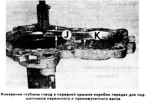
The difference between the dimensions "J" and "G" determines the thickness of the adjusting ring installed on the primary shaft, and the difference between the dimensions "K" and "H" determines the thickness of the adjusting ring installed on the intermediate shaft.
Screw in the reverse light switch and install the gear selector shaft lock.
Heat the inner ring of the ball bearing to 80°C and press it onto the intermediate shaft.
Similarly, press the bearing onto the input shaft using tool 23.1.000.
Press the bearings in until they stop. Install the thrust washers. Lubricate the selected adjusting lugs and put the retaining rings in place.
Install the front cover of the gearbox housing. When installing the bolts for its fastening, consider their dimensions:
- bolts 1-3 (see photo): 8x30 mm;
- bolts 4-7: 8x22 mm.
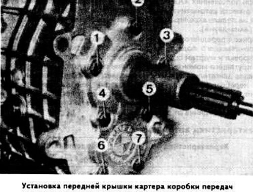
These bolts must be installed with sealant.