
Therefore, the ground wire (-) The battery is also connected to the car body. However, sometimes this earth connection is not enough, and the corresponding consumer is connected directly to the earth by a wire, the insulation of which, as a rule, has a brown color. Switches, relays, fuses, meters, electrical motors, or other electrical components may be connected in a separate electrical circuit. In order to be able to connect these parts correctly, the individual connecting wires are colored differently and the individual contacts are numbered accordingly.
In order to visually streamline the interweaving of wires, at least on the electrical diagram, the entire electrical system of the car is divided into separate circuits. Electrical nodes that are interconnected are depicted in a joint diagram. As a rule, positive ones are shown at the top (+) electrical circuit connectors, while ground connections are indicated below (-). The ground connection is usually made directly through the body or through a wire from the ground connector located on the body.
Attention: The image of nodes and wires in the diagram is not to scale. For example, a wire longer than 1 meter is shown in the same way as a wire only a few centimeters long.
The most important terminal designations:
Terminal 15 is powered by the ignition switch. Current flows through the wires only when the ignition is on. The wires are usually black or black with colored stripes.
Terminal 30. Battery voltage is always connected to this terminal. The wires are mostly red or red with colored stripes.
Terminal 31 is connected to ground. Ground wires are usually brown.
In the electrical diagram, all consumers and switches are shown in a state of rest. The changing current flow after closing the circuit breaker is illustrated by the example of a two-position circuit breaker:
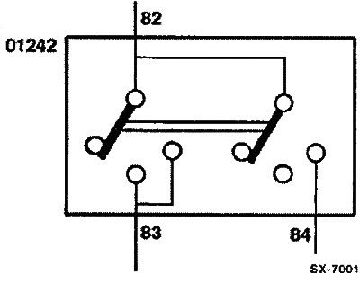
If the switch is pressed into the first position, then the current coming from the B2 terminal flows through the B3 terminal. The second jumper also moves one position, but does not turn on. Only after pressing the switch to the second position, the second jumper connects the internal wire B2 to the wire B4. and now the current through wire B4 is fed further. At the same time, through the internal connection in the switch, the current continues to flow through wire B3.
The following example explains how to read an electrical diagram:
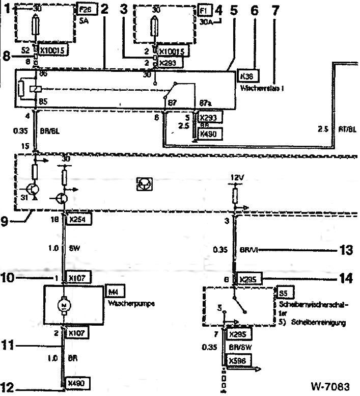
- 1) Terminal designation, here: terminal 30.
- 2) The dashed line between pins B and 2 on the X293 plug indicates that both pins belong to the X293 plug.
- 3) The dashed line from fuse F1 to pin 2 of plug X293 shows the operating power supply of relay K36 positive (+) voltage.
- 4) Permissible current through the fuse, here: 30 amps.
- 5) The circuit breaker and relay are shown always at rest. The circuit element enclosed in a frame by a solid line is presented in full on the diagram, here: K36.
- 6) The designation of the circuit element, here: K36.
- 7) The name of the circuit element, here: wiper relay I.
- 8) The dashed line from fuse F26 to pin B of plug X293 shows the control supply of relay K36 positive (+) voltage.
- 9) The circuit element, framed by a dotted line, is not fully represented on the diagram, here: the main module A1.
- 10) Contact designation.
- 11) The double line from pin 2 of connector XI07 to earth connection X490 shows the earth connection of the windshield washer pump motor M4.
- 12) Ground connection X490.
- 13) Wire color, here: BR/VI - brown / purple.
- 14) Designation of the plug connector, here: X295.
Letter designations of the most important parts:
- A - fuse holder / control unit / module
- B - temperature sensor
- E - lamp
- F - fuse
- H - horn / direction indicator / brake signal
- K - relay
- M - electric motor
- N - radio
- R - potentiometer
- S - switch
- V - valve
- X - plug connector or earth connection
- Y - outside rear view mirror
Wire color code:
- BL - blue
- BR - brown
- GE - yellow
- GN - green
- GR - gray
- RT - red
- SW - black
- VI - purple
- WS - white