
A fan is screwed onto the water pump shaft at the front. This fan serves to provide additional air flow through the radiator. The fan contains a viscous coupling. As soon as the air coming from the radiator reaches a temperature of about 90°C, a bimetallic strip in the viscous coupling turns on the fan. The fan will then rotate at a speed equal to the engine speed and provide additional air flow to the radiator until the temperature of the passing air drops to about 60°C. After this, the viscous coupling is switched off and the fan speed decreases.
Due to the fact that the fan does not operate constantly, the useful power of the engine increases and fuel consumption decreases.
Caution: When the engine is hot, cover the radiator cap with a thick cloth before opening it to avoid being burned by hot coolant or steam. Open the cap only when the coolant temperature is below 90°.
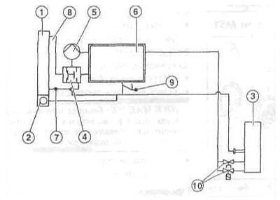
Coolant circulation diagram of the M52 series engine
1 — radiator;
2 - expansion tank;
3 — heater radiator;
4 - thermostat;
5 - water pump;
6 — cylinder block;
7 - Coolant return;
8 - coolant supply;
9 — throttle valve heating;
10 — heater valve (tap).
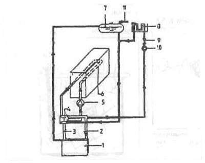
Coolant circulation diagram of the M30 series engine
1 - radiator;
2 - entrance;
3 - exit;
4 - thermostat;
5 - water pump;
6 — channel cylinder block/cylinder head;
7 - expansion tank;
8 — heater radiator;
9 — electromagnetic heating valve;
10 - additional water pump;
11 — exhaust pipe.
A heat accumulator can be installed as additional equipment. Its task is to accumulate heat with the cooling liquid and return it when the cold engine is started.
This allows the heating to work faster and reduces the engine warm-up time. An insulated vessel in the driver's footwell, filled with a chemically stable substance, serves as a heat accumulator. The accumulator is connected in parallel to the coolant circuit and exchanges heat with the coolant. Various electromagnetic valves control the flow of coolant during the accumulation and release of heat.
Cooling system circuit of the M70 series engine - features
The system is closed and has an expansion tank. The expansion tank is located at the rear in the middle of the engine compartment. Coolant is poured only through the expansion tank cap. Thanks to the level control sensor-switch in the expansion tank, the coolant level is monitored.
The coolant pump on the front of the engine circulates coolant through the system.
The radiator on the front panel of the car gives off the heat it produces to the environment. During normal operation of the car, a headwind is enough to cool it.
When the car is stopped or driving slowly, air supply is maintained by a temperature-controlled fan on the water pump axis and an additional fan in front of the radiator.
To heat the interior, a separate pump takes in coolant and passes it through the interior heater radiator.
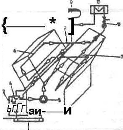
Coolant circulation diagram of the M70 series engine
1 - radiator;
2 — stock;
3 - source;
4 - thermostat;
5 - water pump;
6 — right cylinder head channel;
7 — left cylinder head channel;
8 - connecting pipe to the drain;
9 — expansion tank;
10 — heater radiator;
11 - additional pump with valve.
The original article is posted on the resource bmwman.ru