
A viscous coupling is located in the fan impeller. As soon as the temperature of the air passing through the radiator reaches +82°C, the bimetal switch turns on the viscous coupling.
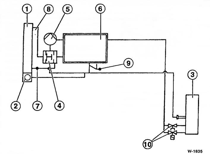
Coolant circuit diagram
1 - radiator
2 - expansion tank
3 - interior heater
4 - thermostat
5 - coolant pump
6 - engine block
7 - fluid outlet from the radiator
8 - fluid supply to the radiator
9 - throttle preheating
10 - heater valves
After that, the fan speed is increased, and it works with increased performance until the air temperature drops below +60°C. In this case, the viscous coupling is switched off and the fan speed is reduced.
Thanks to the fan, which does not always operate at maximum speed, the useful power of the engine is increased and fuel consumption is reduced.
Attention: When the engine is hot, before opening the cap of the expansion tank, in order to avoid burns from hot liquid or steam, cover the cap with a thick rag. Danger of accident! Open the cover only when the coolant temperature is below +90°C.
Work on replacing the coolant and data on the capacity of the cooling system are described in the section "Maintenance work".
As an additional option, a thermal energy accumulator is installed.
It accumulates thermal energy from the coolant, and during the subsequent start-up of a cold engine, it again releases it into the cooling system. Thanks to this, the interior heater starts to function faster and the engine warm-up time is reduced. A thermally insulated container located in the passenger footwell next to the driver, which is filled with a chemically stable and reusable material, serves as a thermal energy accumulator. The accumulator is connected in parallel to the coolant circulation circuit and exchanges heat with the liquid. The control of the flow of coolant through the battery in the process of accumulation and release of heat is carried out automatically using various solenoid valves.