
Withdrawal
Loosen wheel bolts.
Remove decorative cap. Mark the position of the rims on the wheel hubs with paint. Thanks to this, the subsequently balanced wheel is set to the same position.
Raise the rear of the car and remove the wheel.
Release the handbrake.
Remove brake drum.
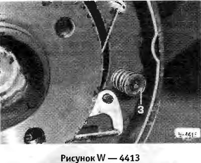
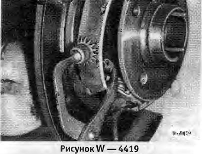
Using pliers, firmly compress the retaining spring cup -3- and turn the cup by 90°. When releasing, press the pin of the spring cup on the rear side of the brake shield.
Disconnect the lower return spring -1- from the front, pull the brake shoe out of the wheel cylinder by hand. Detach top return spring -2- from front. Pull out the front brake shoe with pressure bar.
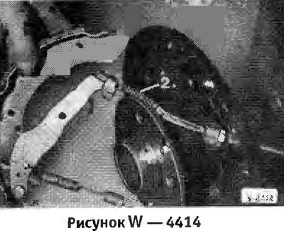
Disconnect the hand wire cable from the hand brake lever by retracting the spring -2- and remove the brake shoe.
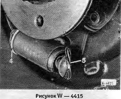
Remove retaining ring -4- from wheel brake cylinder and remove boot -5-.
Caution: The cylinder piston must not protrude while doing this. Check if it is damp behind the boot. If necessary, repair or replace the wheel brake cylinder.
Slide boot onto wheel brake cylinder and secure with circlip.
Installation
Be sure to replace all 4 brake pads at once and use pads from the same manufacturer. Both the brake pads themselves and their linings can be replaced. Blow out the brake drums and brake shields with compressed air or rinse with alcohol. With the brake pads removed, do not press the brake pedal, as the piston will come out of the cylinder. If the wheel brake cylinder is wet with brake fluid, repair the cylinder. Clean push rod threads and lightly lubricate with molybdenum sulfide grease. Scratched drums should be bored, and both drums should be bored at once. The maximum allowable dimension for boring is 229.5 mm.
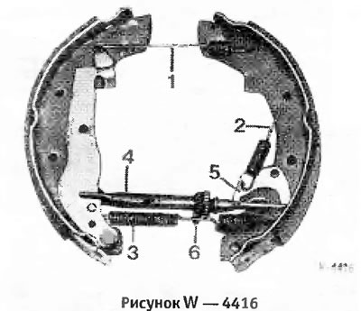
Location of handbrake parts
1. Upper return spring
2. Side return spring
3. Lower return spring
4. Push bar
5. Automatic brake setting lever
6. Thermal clamp
Attention: When replacing the brake pads, the return springs and the thermal clamp are replaced at the same time.
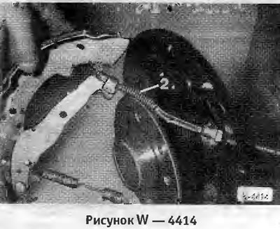
Connect handbrake cable -2- to handbrake lever.
Insert the pin of the spring cup into the hole in the brake shoe from the rear side of the brake shield. Put on the clamping spring. Put on the spring cup with pliers. While holding the pin at the back, rotate the spring cup 90°.
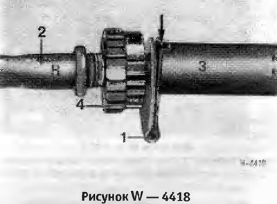
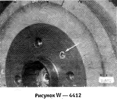
Unscrew pinion -4- for automatic brake setting. Check the ease of movement of the mechanism parts. Lightly lubricate the pressure plate if necessary. The gear on the left wheel has a right hand thread -R- and the gear on the right wheel has a left hand thread.
Attention: The thermal clamp -1- must snap into the recess -arrow- on the pressure plate -3-.
Insert the pressure bar from below into the drum brake.
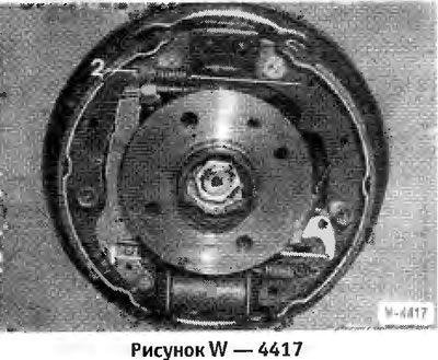
Insert the lever -5- of the automatic brake setting mechanism and secure with the return spring -2-.
Attention: Ensure the correct position of the return spring -2- (Drawing W 4416).
Insert the pin of the spring cup into the hole of the brake shoe from the rear side of the brake shield. Put on the clamping spring. Put on the spring cup with pliers. While holding the pin at the back, rotate the spring cup 90°.
Connect the top and bottom return springs.
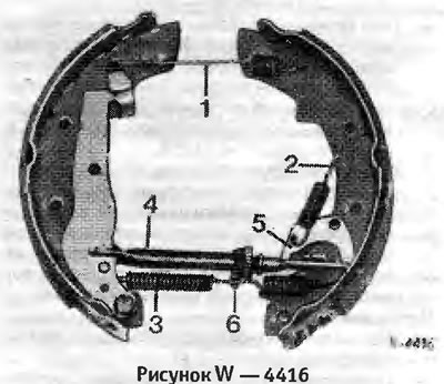
When installing return springs -1- and -3- pay attention to the position of the bends.
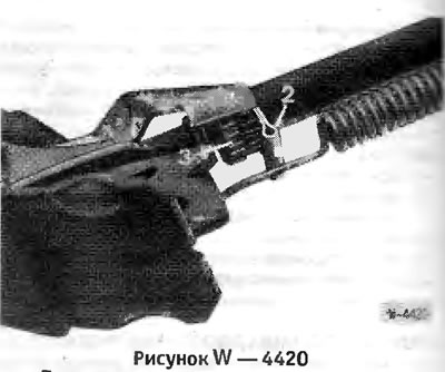
Check whether the automatic brake setting mechanism is engaged with the pinion -3- and whether the thermal clamp -2- is in the recess.
Install the brake drum and turn it so that the hole in the brake drum aligns with the threaded hole in the flange. Tighten the brake drum mounting bolt with a 5 mm spanner.
If the hydraulic circuit is opened, for example when replacing a wheel brake cylinder, the brake system must be bled before adjusting the rear wheel brake.
Press the brake pedal repeatedly to install the brake pads.
Before the brake pads are installed, clicks will be heard from the brake side of the rear wheel. Through the hole for the wheel bolt, you can see how the brake pad setting mechanism works.
Adjust handbrake.
Place the wheel in compliance with the marked position of the disk on the hub.
Lower vehicle and cross-tighten wheel bolts to 110 Nm.