
Withdrawal
Interior door handle
1. The inner door handle is part of the cladding and cannot be replaced separately.
Front door lock assembly
2 Lower the glass completely, then raise it approximately 140 mm (when measured along the trailing edge of the glass). Remove the door lining (see paragraph 12). To access the lock components, carefully remove the soundproofing cover, then refer to the relevant part of this paragraph. If the soundproofing is damaged when removed, replace it.
3. Loosen glass clamps (see fig. 14.5, a, b) and secure the glass with adhesive tape in the raised position. Remove the two nuts securing the rear glass support bracket and lower the bracket into the bottom of the door. It is not necessary to remove the glass guide (see fig. 14.8).
4. When removing the lock in the driver's door, remove the lock cylinder (see p.p. 13-15).
5. Release the clamps of the electrical wiring of the lock assembly and disconnect the connector (s) wiring.
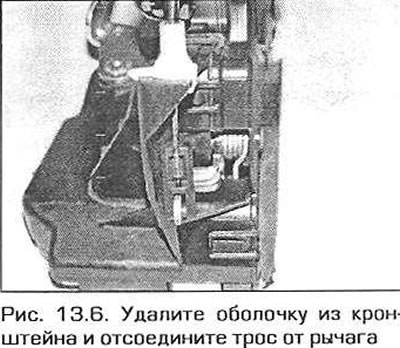
6. On models manufactured since September 2000, remove the cable sheath from the bracket and disconnect the cable from the lock (pic. 13.6).
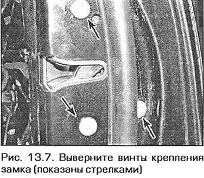
7. Remove the lock fixing screws, then pass the lock behind the glass guide and remove the lock assembly with the lock button rod from the door opening (pic. 13.7).
External front door handle (models released before September 2000)
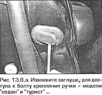
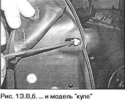
8. When removing the driver's door handle, first remove the lock cylinder (see p.p. 13-15). When removing the passenger door handle, remove the plug located at the end of the door to access the handle mounting bolt. On the model "coupe" gently fold back the top of the rubber door seal to access the plug. Turn out a bolt and remove a back casing of the external handle (pic. 13.8, a, b).
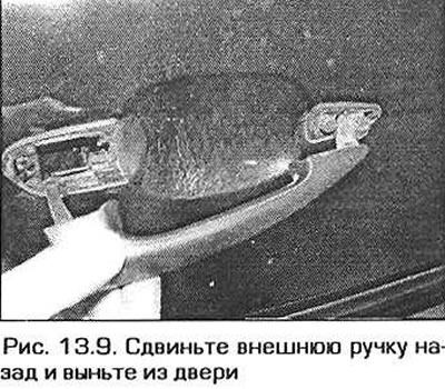
9. Pull the handle out and slide it back about 2 mm. This will engage the locking mechanism. Push the handle inward about 4 mm, then slide it back and out of the door (pic. 13.9).
External front door handle (models produced since September 2000)
10. When removing the driver's door handle, first remove the lock cylinder (see p.p. 13-15). When removing the passenger door handle, remove the plug located at the end of the door to access the handle mounting bolt. On the model "coupe" gently fold back the top of the rubber door seal to access the plug. Turn out a bolt and remove a back casing of the external handle.
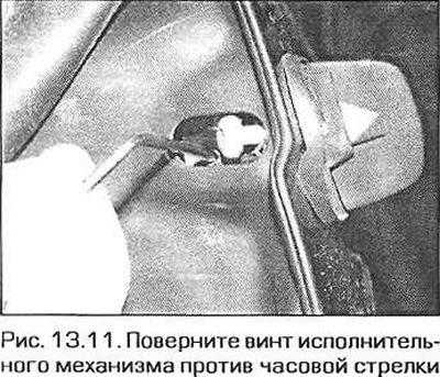
11. The castle must remain in place. Pull the handle out and place a piece of wood or a rag under it. Through the hole in the end of the door, turn the screw of the actuator counterclockwise until it stops (pic. 13.11). Take out the wooden block (or a rag).
12. Pull out the back of the handle, then remove the handle from the door.
Front door lock cylinder
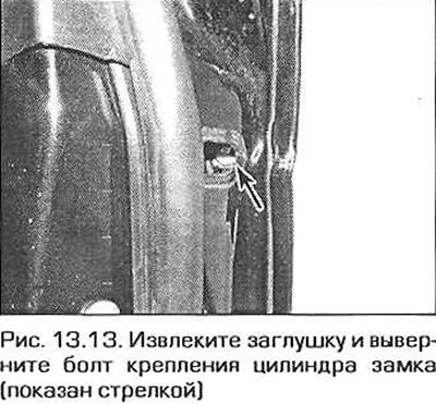
13. To access the lock cylinder, remove the plug from the end of the door (pic. 13.13). On the model "coupe" gently fold back the top of the rubber door seal to access the plug.
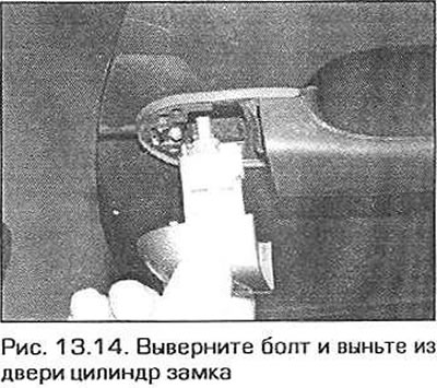
14. Using a hex key, unscrew the bolt and remove the lock cylinder from the door (pic. 13.14).
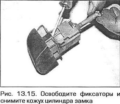
15. If necessary, release the two latches and disconnect the plastic casing from the cylinder (pic. 13.15).
Rear door lock
16. Remove the door lining and soundproofing (see paragraph 12). Disconnect the connector (s) wiring from the door lock.
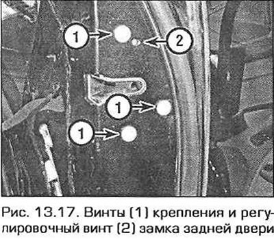
17. Turn out screws of fastening of the lock, then take out the lock from a door together with draft of the button of blocking (pic. 13.17).
Exterior tailgate handle (models released before September 2000)
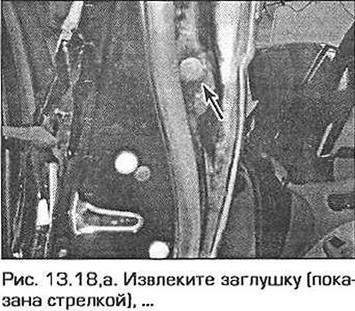
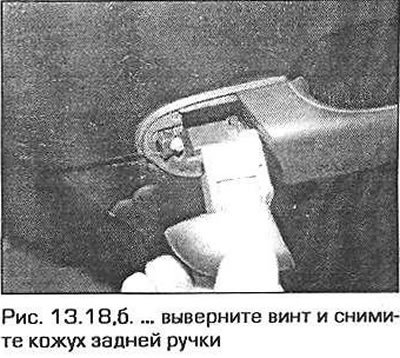
18. For access to a bolt of fastening of a back casing of the handle take out a cap from an end face of a door. Loosen the bolt and remove the rear cover (pic. 13.18, a, b).
19. Pull the handle out and slide back approximately 2 mm. This will engage the locking mechanism. Push the handle inward about 4 mm, then slide it back and out of the door (see fig. 13.9).
Exterior tailgate handle (models produced since September 2000)
20. For access to a bolt of fastening of a back casing of the handle take out a cap from an end face of a door. Turn out a bolt and remove a back casing.
21. The castle must remain in place. Pull the handle out and place a piece of wood or a rag under it.
22. Through the hole in the end of the door, turn the screw of the actuator until it stops counterclockwise (see fig. 13.11). Take out the wooden block (or a rag).
23. Pull out the back of the handle, then remove the handle from the door.
Installation
Interior door handle
24. The inner door handle is part of the cladding and cannot be replaced separately.
Front door lock assembly
25. Remove traces of old sealant from the lock screws.
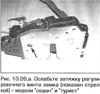
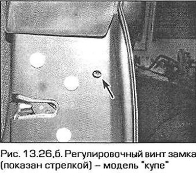
26. Before installing the lock, loosen the adjusting screw. In the lock of the right door, this screw has a left-hand thread, and in the left door it has a right-hand thread (pic. 13.26, a, b).
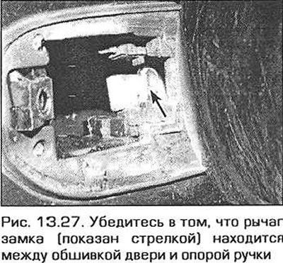
27. Replace the lock assembly. Make sure the lock button rod is in the hole in the door. Make sure. that the lock lever is located between the door trim and the handle support (pic. 13.27).
28. Apply some sealant to the lock screws (BMW recommends Loctite 270), then screw in the screws and tighten them to the required torque.
29. Connect the connector (s) wires and secure the wires with appropriate brackets.
30. Install the lock cylinder in the driver's door (see p.p. 43-45).
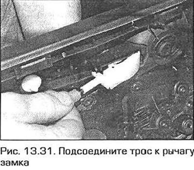
31. On all models manufactured since September 2000, connect the cable to the lock lever and attach the cable sheath to the bracket (pic. 13.31).
32. Install the glass and rear guide, screw the nuts and tighten them securely. Lower the glass and insert it into the clips (see paragraph 14).
33. Do not close the door until you have adjusted and checked the operation of the lock as follows.
- A) To access the adjusting screw, remove the plastic cap located opposite the top screw of the lock (see fig. 13.26, a, b).
- b) In the left door screw in the adjusting screw until it stops clockwise. In the driver's door, turn the adjusting screw counterclockwise until it stops.
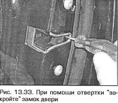
- V) With a screwdriver "close" door by pressing the lock lever (pic. 13.33).
- G) Use the key to open the lock.
- d) With external handle "open" door.
- e) If the lock does not open, loosen the adjusting screw, then retighten it. Check the operation of the lock.
- and) Do not close the door until the lock has been adjusted. If you accidentally close the door, you may need to cut the outer skin of the door to open it.
- h) Replace the plastic cap.
34. Install soundproofing on the door. Install the door trim (see paragraph 12).
External door handle (models released before September 2000)
35. Make sure the lock lever is correctly positioned (see fig. 13.27). If the lever is not positioned correctly, use a screwdriver to turn the lock lever outward.
36. Insert the front of the handle into the door, then the back. Press the handle against the door and slide it forward until "clicks".
37. When installing the handle on the driver's door, first install the lock cylinder (see p.p. 43-45). When installing the handle on the passenger door, install the rear handle cover first, and securely tighten the fixing bolt. Install the plug in the door hole.
38. Do not close the door until you check the operation of the lock (see par. 33). Install soundproofing on the door. Install the door trim (see paragraph 12).
External front door handle (models produced since 2000)
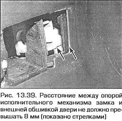
39. Before installing the handle, the door lock must be in place. The distance between the lock actuator support and the outer skin of the door must not exceed 8 mm (pic. 13.39). If this distance is greater than specified, slide the support outward with your finger.
40. Insert the front of the handle into the hole in the door, then insert the back of the handle into the door. Make sure that the seal between the handle and the door skin has not moved. Screw in the lock adjusting screw clockwise until it stops.
41. When installing the handle on the driver's door, install the lock cylinder (see p.p. 43-45). When installing the handle on the passenger door, install the rear handle cover first, and securely tighten the fixing bolt. Install the plug in the door hole.
42. Do not close the door until you check the operation of the lock (see par. 33). Install soundproofing on the door. Install the door trim (see paragraph 12).
Front door lock cylinder
43. Install the plastic casing on the lock cylinder (if it was taken).
44. Lubricate the outer surface of the lock cylinder.
45. Insert the cylinder into the lock and tighten the fastening screw securely. Insert a plastic plug into the door. Before closing the door, check the operation of the lock (see paragraph 33).
Rear door lock
46. Remove traces of old sealant from the lock screws.
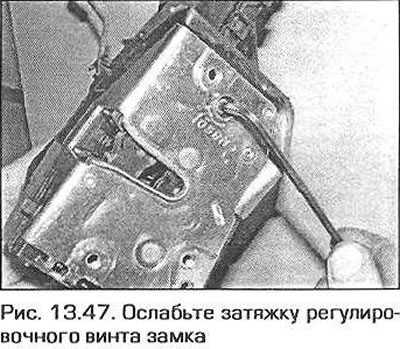
47. Before installing the lock, loosen the adjusting screw. In the lock of the right door, this screw has a left-hand thread, and in the left door it has a right-hand thread (pic. 13.47).
48. Install the lock assembly in place. Make sure the lock button rod is in the hole in the door. Make sure the lock rod is between the door trim and the handle support.
49. Apply some sealant to the lock screws (BMW recommends Loctite 270), then screw in the screws and tighten them to the required torque. Plug connector (s) wires and secure the wires with appropriate brackets.
50. On all models manufactured since September 2000, connect the cable to the lock lever and attach the cable sheath to the bracket.
51. Check the operation of the lock (see par. 33).
52. Install soundproofing on the door. Install the door trim (see paragraph 12).
Exterior tailgate handle (models released before September 2000)
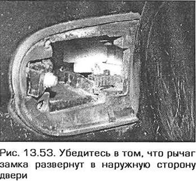
53. Make sure the lock lever is correctly positioned (pic. 13.53). If the lever is not positioned correctly, use a screwdriver to turn the lock lever outward.
54. Insert the front of the handle into the door, then the back. Press the handle against the door and slide it forward until "clicks".
55. Install the rear handle cover, and securely tighten the mounting bolt. Install the plug in the door opening.
56. Do not close the door until then. until you check the operation of the lock (see par. 33).
57. Install soundproofing on the door. Install the door trim (see paragraph 12).
Exterior tailgate handle (models produced since September 200D)
58. Before installing the handle, the door lock must be in place. The distance between the lock actuator support and the outer skin of the door must not exceed 8 mm (pic. 13.39). If this distance is greater than specified, slide the support outward with your finger.
59. Insert the front of the handle into the hole in the door, then insert the back of the handle into the door. Make sure that the seal between the handle and the door skin has not moved.
60. Install the back cover of the handle, and securely tighten the mounting bolt. Install the plug in the door hole.
61. Do not close the door until you check the operation of the lock (see par. 33).
62. Install soundproofing on the door. Install the door trim (see paragraph 12).