
- Home
- BMW 3 Series
- E46
- Chassis
- Wheel suspension
- Upper arm rear suspension — removal, repair and installation
Upper arm rear suspension — removal, repair and installation (BMW 3 Series E46)
Note: When installing you will need a new bolt and nut to secure the upper arm to the subframe.
Removal
1. Remove the suspension spring (see paragraph 12).
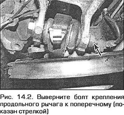
2. Unscrew the bolt securing the longitudinal arm to the transverse arm (Fig. 14.2). Remember the location of the bolt.
3. Support the final drive unit with a jack (see chapter 8). Loosen the final drive mounting bolts so that the assembly can be moved when removing the axle bolt. Alternatively, remove the drive shaft (see chapter 8).
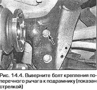
4. Loosen the nut of the axle bolt connecting the wishbone to the subframe. Remove the bolt by slightly moving the final drive assembly back and remove the wishbone from the vehicle (Fig. 14.4). Note that on some models this requires disconnecting the propeller shaft.
Note: If you remove the lever for an indefinite period of time, reinsert it and tighten the final drive mounting bolts securely.
Repair
5. Thoroughly clean the lever and the area around the fasteners. Remove all traces of dirt and sealant. Check for damage, wear, paying particular attention to the support bushings. If the bushings need replacing, contact a specialized service station, as this work requires a hydraulic press and a set of spacer bushings (for pressing in new bushings).
6. Inspect the bolts and make sure they are not damaged or worn. Replace the bolts if necessary. The bolt and nut that secure the arm to the subframe must be replaced regardless of their condition.
Installation
7. Install the lever in place, insert the new axle bolt securing the lever to the subframe and screw on the nut. Do not tighten the nut yet.
8. Install the main gear in place and tighten its mounting bolts to the required torque. Connect the cardan shaft to the main gear (if it was disconnected).
9. Insert (from the rear) the bolt securing the upper arm to the trailing arm, screw it on (but don't delay) nut.
10. Install the suspension spring (see paragraph 12).
11. Once assembly is complete, lower the vehicle to the ground and rock it to ensure that the suspension assemblies are in working position. Tighten the wheel mounting bolts, lower shock absorber support bolt, and wishbone axle bolts to the specified torque.
Note: After completing the work, check and, if necessary, adjust the rear wheel alignment angles.
This article is available at russian, bulgarian, belarusian, ukrainian, serbian, croatian, romanian, polish, slovak, hungarian
Article verified: Ilyinsky Matvey
Share information:
Previous articles
БМВ E46: Wheel suspension
Next articles
Similar articles on other types of BMW cars:
Removal and installation the upper shock absorber support and… BMW 5 Series E12 (1972-1981)
Removal and installation, inspection of the rear shock absorber BMW 5 Series E34 (1988-1996)
Rear suspension assembly — removal and installation BMW 7 Series E32 (1986-1994)
Removal and installation the rear suspension beam assembly BMW 7 Series E38 (1994-2001)
Removal and installation the rear door BMW X3 E83 (2003-2010)
Rear disc — removal and installation BMW X5 E53 (1999-2006)
Link in different formats to this page
Visitor comments
No comments yet
- General information
- Manual
- Maintenance
- Power unit
- Engine repair
- Cooling system
- Power system (gasoline)
- Injection system (gasoline)
- Fuel system (diesel)
- Exhaust system
- Ignition system
- Charge and launch systems
- Transmission
- Car gearbox
- Clutch and drive shafts
- Chassis
- Brake system
- Suspension front and rear
- Steering
- Body
- Body care and repair
- Exterior
- Interior
- Electrical equipment
- Troubleshooting
- Lighting and signaling
- Equipment and devices
- Heater and air conditioner
- Electrical circuits
- General information
- Manual
- Repair on the road
- Weekly checks
- Maintenance
- Troubleshooting
- Power unit
- 4 cylinder engines
- 6 cylinder engines
- Engine overhaul
- Cooling and heating
- Fuel and exhaust system
- Starting and charging system
- Ignition system
- Transmission
- Clutch
- Mechanical gearbox
- Automatic gearbox
- Cardan and drive shafts
- Chassis
- Brake system
- Wheel suspension
- Steering
- Body
- Exterior
- Interior
- Electrical equipment
- Equipment and devices
- Electrical circuits
- General information
- Maintenance
- Power unit
- Engine repair
- Cooling system
- Ignition system
- Supply system
- Fuel injection system
- Exhaust system
- Transmission
- Clutch
- Car gearbox
- Front and rear axle
- Chassis
- Steering
- Brake system
- Body
- Exterior
- Interior
- Electrical equipment
- Heating system
- Equipment and devices
- Power devices
- Electrical circuits
- Power unit
- M10/M20 engine
- M40 engine
- Ignition system
- Lubrication system
- Cooling system
- Supply system
- Fuel injection
- Exhaust system
- Transmission
- Clutch
- Manual gearbox
- Front axle
- Rear axle
- Chassis
- Steering
- Brake system
- Body
- Exterior
- Interior
- Electrical equipment
- Heating system
- Equipment and devices
- Electrical circuits
- General information
- Specifications
- Operation and maintenance
- 4-cylinder engine
- Engine repair
- Cooling and lubrication system
- Supply system
- Ignition system
- 6-cylinder engine
- Engine repair
- Cooling and lubrication system
- Supply system
- Fuel injection system
- Ignition system
- Transmission
- Clutch
- 4-speed manual gearbox
- 5-speed manual gearbox
- Automatic gearbox
- Cardan and rear axle
- Chassis
- Steering
- Front suspension
- Rear suspension
- Brake system
- Electrical equipment
- Equipment and devices
- Electrical circuits