



The ABS system prevents the wheels from locking during sudden braking. Thanks to this, the car remains fully controllable during full braking.
The ABS system is ready to operate when the ignition is turned on and at speeds starting from 57 km/h. It controls all braking processes in the locking area after speeds exceeding 12 km/h.
The speed sensors located on each wheel measure the rotation speed of the wheels. Based on the signals from individual wheels, the control unit calculates the average speed, which roughly corresponds to the speed of the vehicle. By comparing the rotation speed of an individual wheel with the average rotation speed of all wheels, the electronic control unit determines the state of wheel slippage and can thus determine that the wheel is approaching a locking state.
As soon as the locking starts, i.e. when the pressure in the brake caliper is still too high in relation to the wheel's grip on the road surface, the control unit maintains the fluid pressure constant based on the signals from the speed sensors. This means that the pressure in the brake caliper does not increase even when the brake pedal is pressed harder. If the tendency to lock does not disappear, the brake fluid pressure is reduced by opening the release valve. In this case, it opens just enough for the wheel to start rotating again, then the pressure is again maintained constant.
If the wheel speed exceeds a certain value, the hydraulic system increases the pressure again, but not exceeding the braking pressure value that is created by the driver when pressing the brake pedal.
This process is repeated for each wheel until the brake pedal is released or until the vehicle is nearly stopped (5-7 km/h).
The control circuit in the electronic control unit ensures that the ABS system is switched off in the event of its failure (for example, a broken wire) or when the supply voltage drops (battery voltage below 10.5 volts), which is indicated by the ABS warning light on the dashboard lighting up. In this case, the vehicle's braking behavior is the same as if the ABS system was not installed.
The hydraulic unit consists of a pump and electromagnetic valves for the front and rear wheel brakes.
Pressure increase: The inlet valve in the solenoid valve is open. The brake fluid pressure in the brake caliper can rise to a value determined by the brake master cylinder.
Pressure stabilization: The inlet and outlet valves in the electromagnetic valve are closed. The brake fluid pressure in the brake caliper does not change, even if the pressure difference between the master cylinder and the electromagnetic valve increases.
Pressure release: The release valve in the solenoid valve is open. Brake fluid flows through the accumulator to the scavenge pump, which pumps out the fluid, overcoming the pressure in the master cylinder.
This is necessary to ensure that all the brake fluid is not pumped out of the main brake cylinder. The pump's operation is felt by the pulsations of the brake pedal. The noise of the pump is damped by dampers in each brake circuit.
When the ABS warning light comes on, pay attention to the following points:
Stop the car, turn off the engine and start it again.
Check the battery voltage. If the voltage is less than 10.5 V, charge the battery.
Caution: If the ABS warning light comes on at the start of a journey and then goes out, this means that the battery voltage was initially low and then increased due to charging from the alternator.
Raise the car, remove the wheels, check the integrity of the electrical wires of the speed sensors (absence of abrasions).
Further checks of the ABS system should be carried out at a service station.
Caution: Before carrying out electric welding work, the connector of the electronic control unit must be disconnected. The connector must be disconnected only when the ignition is switched off. During painting work, the control unit may only be exposed to short-term temperatures of up to a maximum of 95°C and long-term temperatures of up to 100°C (approximately up to 2 hours) exposure to temperatures up to a maximum of 85°C.
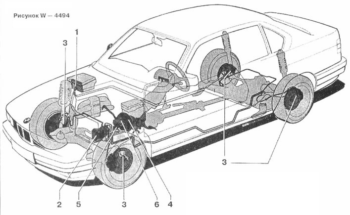
Figure W - 4494. ABS system
1 Electronic control unit
2 Hydraulic unit
3 Speed sensor
4 Hydraulic brake booster
5 Master brake cylinder
6 Expansion tank with brake fluid