
Note: The intake or exhaust camshaft can be replaced directly on the vehicle.
Caution: If the camshaft is removed/installed incorrectly and without the appropriate tools, there is a risk of damage or breakage of the camshaft. In addition, when in contact with the piston bottom, the valves can become deformed. It is imperative to follow the instructions, use special tools and maintain the sequence of operations.
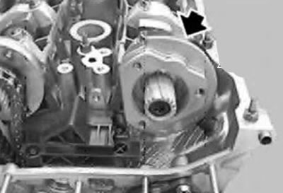
1. Remove the VANOS system actuator.
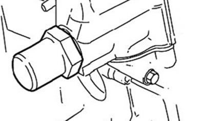
Caution: The chain tensioner plunger cylinder is spring-loaded.
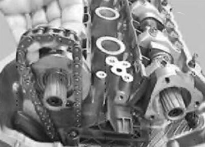
2. Remove the chain tensioner plunger cylinder.
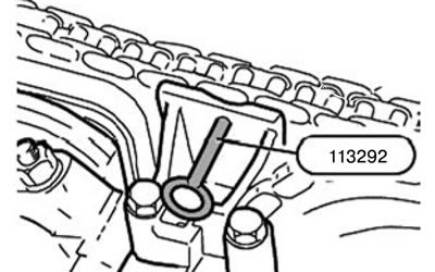
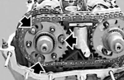
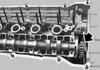
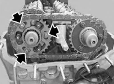
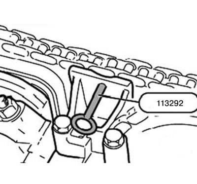
3. Press the upper secondary chain tensioner down and lock it with tool 113292.

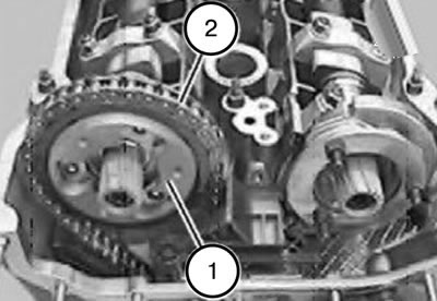
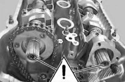
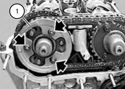
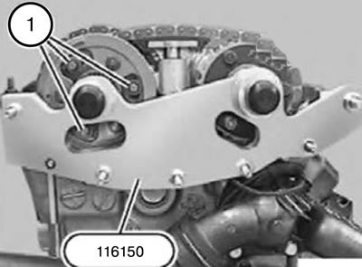
4. Loosen the nuts and remove the sensor wheel (1).
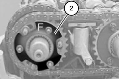
5. Remove the disc spring (2).
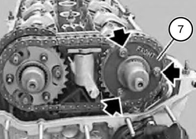
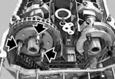
6. Loosen the nuts on the intake side and remove the washer (7).
7. Remove the screws.
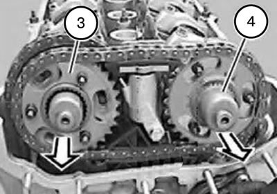
8. Remove the intake and exhaust camshaft chain drive sprockets together with the chain, thrust plate (3) and splined shaft (4).
Note: The splined shafts (4) for the exhaust side and intake side are the same. Used splined shafts should be set aside in strict order and subsequently installed only on the same side.
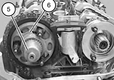
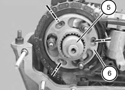
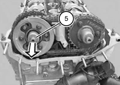
9. Remove the splined shaft (5) with the toothed sleeve (6).
10. Remove the screws. Remove the secondary chain tensioner.
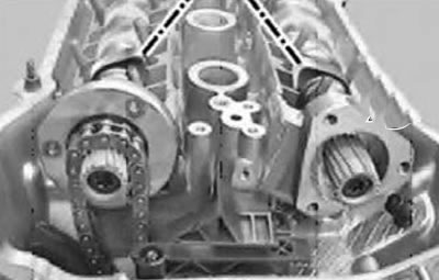
11. Unscrew the pins.
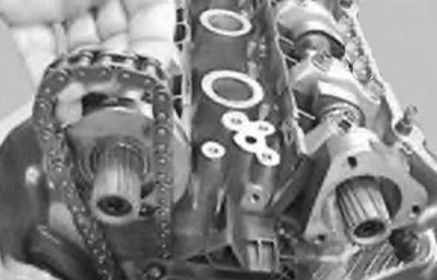
12. Disconnect the sprocket (1) from the drive chain (2) forward.
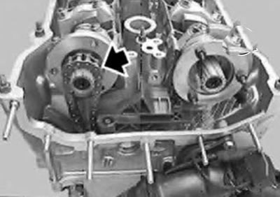
Note: The timing chain remains above the exhaust camshaft.
13. If necessary, unscrew the studs on the intake side.
14. Remove the thrust disc.
15. Remove the wheel with the camshaft position sensor.
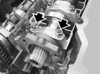
Caution: Do not remove these bolts.
16. Unscrew the mounting pins.
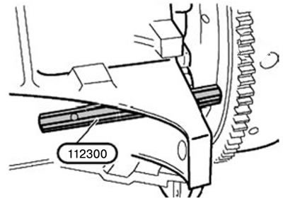
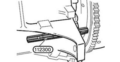
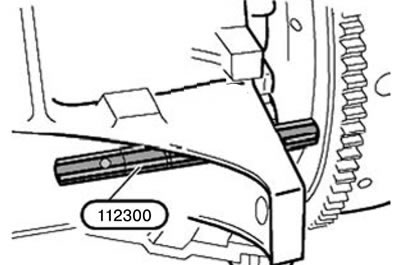
17. Pull tool 112300 back just enough to release the flywheel.
Caution: To avoid damaging the valves when installing the camshafts, make sure none of the pistons are in the TDC position.
18. Pull the drive chain up and hold it taut.
19. Turn the crankshaft by the central bolt against the direction of rotation by approximately 30°.
Attention:
- The cover of the 1st bearing of the intake camshaft is centered using centering bushings.
- To avoid distortion of the intake camshaft in the support bar, unscrew the nuts and remove the bearing cover 1.
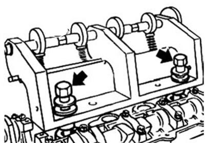
20. Install tool 113260 on the cylinder head and secure it with bolts in the threaded holes for the spark plugs of cylinders 1 and 4.
21. Turn the eccentric shaft; pre-tension is created on the bearing caps.
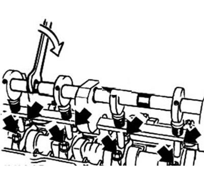
22. Loosen the bearing cap fastening nuts.
23. Loosen the tension of the eccentric shaft and remove tool 113260.
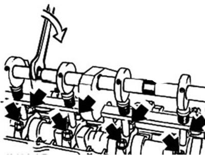
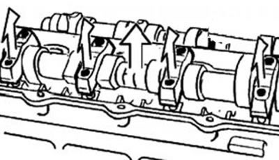
24. Remove the bearing caps and set them aside in strict order.
25. Remove the camshaft.
Note: If you then need to remove the cylinder head, remove the support bar assembly with the plate tappet.
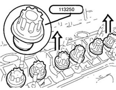
26. Secure the plate tappets in the support bar using tool 113250.
27. Remove the support bar assembly together with the plate tappet.
Note: Used tappets should only be installed in the same holes.
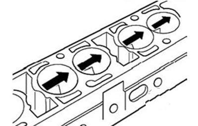
28. Check the support areas of the plate tappets for wear (scratches).
29. The support strips are marked "A" for the exhaust side and "E" for the intake side.
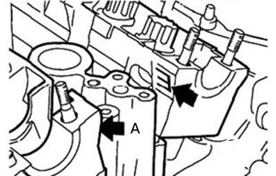
30. Pay attention to the centering bushings on the bearing mounting studs 2 and 7.
31. Install the support strips.
Note: Lubricate camshafts, bearings and bearing caps, thrust discs, splined shaft gear rings and splined bushings before installation.
Caution: Without camshaft load, the bucket tappets stretch and require some time to recompress after installation. Therefore, during quick installation, the "closed" valves may remain open and come into contact with the piston.
Note:
After installing the camshaft and before turning the engine crankshaft against the direction of rotation to set the pistons to TDC, wait for the following waiting time:
- at room temperature (20°C) 4 min;
- at a temperature of 10°C - 20°C 11 min;
- at a temperature of 0°C - 10°C 30 min.
32. Pull the drive chain up and insert the exhaust camshaft.
33. Place the drive chain on the exhaust camshaft.
34. Insert the camshafts so that the tops of the camshaft cams of the intake and exhaust valves of the 1st cylinder are facing each other.
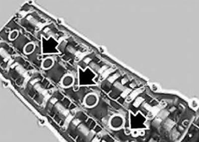
35. Install the bearing caps.
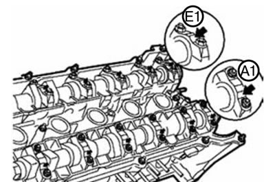
Note: Bearing caps are marked on the exhaust side.
- A1 - A7 for the release side.
- E1 - E7 for the intake side.
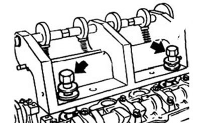
36. Install tool 113260 on the cylinder head and secure it with bolts in the threaded holes for spark plugs of cylinders 1 and 4.
37. Turn the eccentric shaft; pre-tension is created on the bearing caps.
38. Tighten the bearing cap mounting bolts.
Tightening torque: 20 Nm.
39. Remove tool 113260.
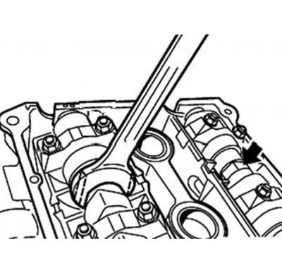
Attention:
- Avoid damaging the cylinder head.
- If necessary, modify the wrench.
40. Center the camshafts using a wrench.
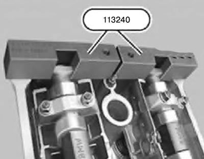
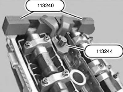
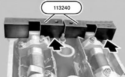
41. Install tool 113240 on the camshafts in the area of cylinder 6.
42. Adjust the position of the camshafts so that tool 113240 fits against the cylinder head without clearance.
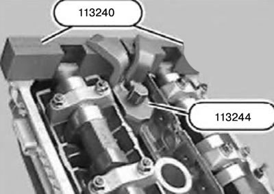
43. Install tool 113244 onto tool 113240 and secure with a bolt in the threaded hole for the spark plug.
44. Pull the drive chain up and hold it taut.
45. Turn the crankshaft from the 30° before TDC position in the direction of rotation to the TDC position.
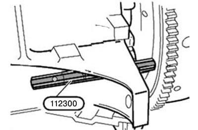
46. Lock the crankshaft at TDC at the end of the compression stroke using tool 112300.
Caution: Remove tool 112300 before starting the engine.
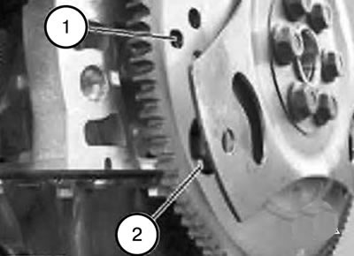
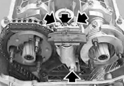
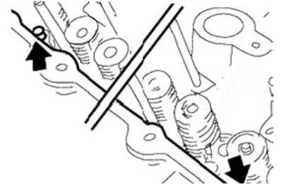
Note: The picture shows without automatic transmission.
Attention:
- On engines with automatic transmission, next to the hole (1) for fixing there is a large hole (2), which can be confused with the hole for fixing.
- When tool 112300 is installed in the correct hole (1), the engine no longer rotates by the central bolt.
47. Install the position sensor wheel on the intake camshaft.
48. Install the thrust disc and tighten it with the mounting bolts.
Tightening torque:
- M7: 20 Nm.
- MB: 10 Nm.
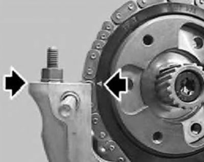
49. Place the drive chain on the sprocket so that the arrow on the sprocket faces the top surface of the cylinder head.
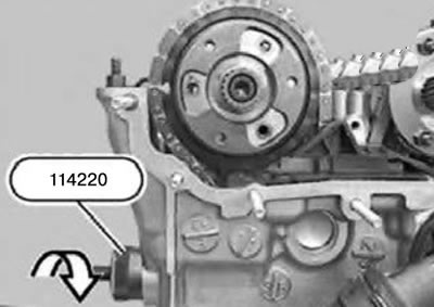
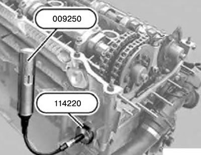
50. Insert tool 114220 into the hole in the cylinder head and screw in the adjusting bolt until it fits, without tensioning the drive chain.
51. Check the position of the arrow on the sprocket relative to the top surface of the cylinder head; if necessary, remove and reinstall the sprocket.
52. Insert and tighten the studs.
Tightening torque:
- M7: 20 Nm.
- M6: 10 Nm.
53. Install the secondary chain tensioner.
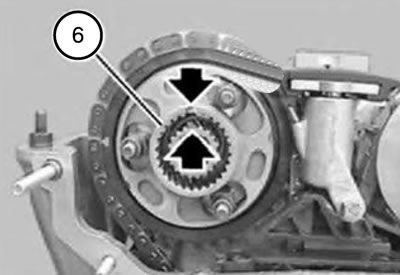
54. Install the toothed sleeve (6) and align it with the splined shaft on the camshaft so that the gaps between the teeth are located on top of each other.
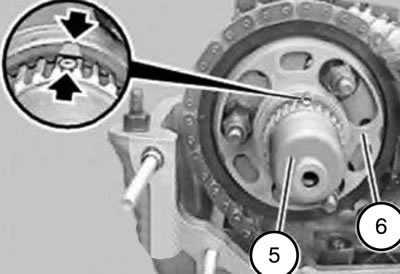
55. Install the splined shaft (5).
56. Mate the spline shaft pin (5) with the gap between the teeth of the camshaft and the toothed sleeve {6).
57. Insert the splined shaft (5) so that the longitudinal holes of the toothed sleeve (6) are aligned with the thread.
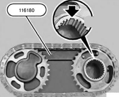
58. Insert the sprockets into tool 116180, set the gap between the teeth on the intake camshaft chain drive sprocket as shown in the figure, and put the chain on.
Caution: Do not change the position of the sprockets relative to the chain when removing from tool 116180.
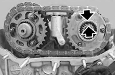
59. Without changing the position, remove the chain with sprockets from the device 116180 and install it so that the gaps between the teeth on the intake side are opposite each other.
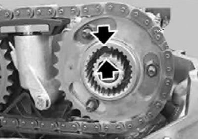
60. Adjust the position of the chain with sprockets so that the gaps between the teeth on the release side are located exactly one above the other.
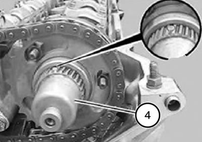
61. Install the splined shaft (4).
62. Align the spline shaft pin (4) with the gap between the teeth of the camshaft and sprocket.
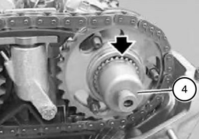
63. Insert the splined shaft (4) so that there is still approx. 1 mm gear ring.
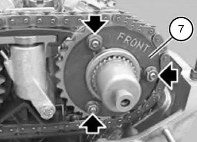
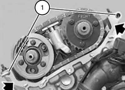
64. Observe the installation position of the washer (7), the inscription "FRONT" must be visible.
65. Install the washer, install the nuts and tighten by hand without tightening completely.
66. Insert the bolts on the outlet side, screw them in until they are tight with a torque of approx. 5 Nm and then loosen again by half a turn.
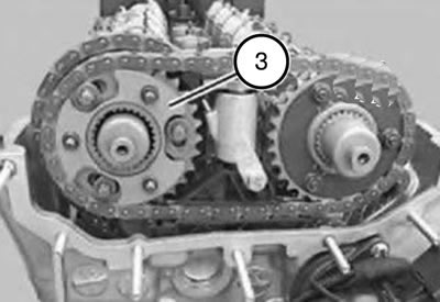
67. Install the thrust disc (3).
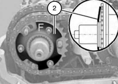
68. Observe the installation position of the disc spring (2), the inscription "F" must be visible.
Note:
- If the "F" inscription has been erased (on a used engine):
- Install the disc spring (2) so that it faces the camshaft position sensor wheel with the smaller diameter support surface (2).
69. Install the disc spring (2).
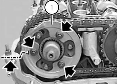
70. Install the camshaft position sensor wheel (1) so that the arrow on the wheel faces the top surface of the cylinder head.
71. Screw on the nut and tighten it by hand without tightening it completely.
72. Pull out the splined shaft (5) until it stops.
73. Press the upper secondary chain tensioner down and remove tool 113292.
74. Pre-tension the tensioner bar using tool 114220 by screwing in the adjusting bolt using tool 009250 or a conventional torque wrench, applying a force of 0.7 Nm.
75. By pressing on the wheel (1) of the camshaft position sensor, create a slight tension on the disc spring and tighten the nuts manually.
Caution: Do not tighten the nuts completely.
76. Remove the seal.
77. Check the centering bushings (1) for damage and correct installation.
Note: The sealing surface must be clean and free of oil.
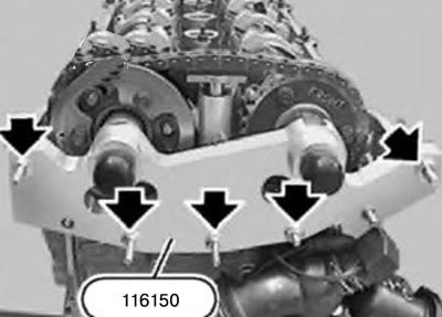
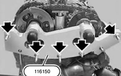
Attention:
- Install tool 116150 only "without seal".
- If there is a seal under the 116150 tool, the valve timing will be adjusted "incorrectly".
78. Install tool 116150 "without seal", screw on the nuts, tighten by hand and then tighten evenly so that tool 116150 fits against the cylinder head over the entire surface.
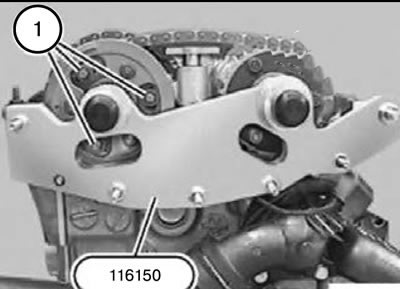
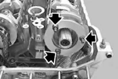
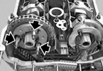
79. Tighten the bolts (1) on the outlet side with a torque of approx. 5 Nm before contact.
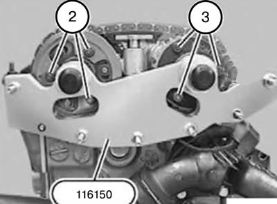
80. Tighten the nuts (2) on the outlet side and the nuts (3) on the inlet side to a torque of approx. 5 Nm before contact.
81. Tighten the bolts (1) on the exhaust side.
Tightening torque: 5 Nm + 20 Nm.
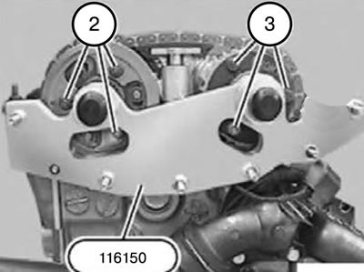
82. Tighten the nuts (2) on the outlet side and the nuts (3) on the inlet side.
Tightening torque:
- M7: 20 Nm.
- M6: 10 Nm.
83. Pull tool 112300 back just enough to release the flywheel.
84. Remove tool 113244 and tool 113240.
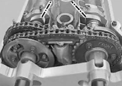
85. Turn the engine shaft twice in the direction of rotation so that the tops of the camshaft cams of the intake and exhaust valves of the 1st cylinder are again facing each other.
86. Lock the crankshaft at TDC at the end of the compression stroke using tool 112300.
Attention:
- Do not allow the engine to turn in the opposite direction.
- Before starting the engine, remove tool 112300.
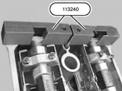
87. Install tool 113240 on the camshafts.
Note:
- The valve timing adjustment is correct if the 113240 tool fits onto the cylinder head without gaps, or is raised relative to the intake side by a maximum of 1 mm.
- If tool 113240 protrudes on the exhaust side, the valve timing must be readjusted.
88. Remove tool 116150.
89. Install the VANOS system actuator.
90. Assemble the engine.
[Original publication posted on the website «bmwman.ru»]