
Description
1. The N42 engine is equipped with a variable intake valve stroke system known as Valvetronic. The purpose of the system is to increase the power and efficiency of the engine, as well as to reduce the amount of harmful emissions in the exhaust gases. In this system, the stroke and duration of the open state of the intake valves is controlled by an electronic device. The range of valve opening regulation is quite sufficient so that the traditional throttle valve can be abandoned. In the Valvetronic system, there is an intermediate lever between the camshaft cam and the valve rocker, which transmits movement from the cam to the rocker at one end, and rests on the eccentric at the other end. The eccentric shaft can be rotated using a special electric motor, which is controlled by the Valvetronic electronic unit (pic. 10.1).
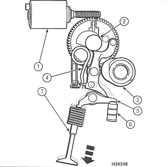
Pic. 10.1. Valvetronic Valve Stroke Actuator
1 control motor
2 Eccentric shaft
3 Camshaft
4 Spring
5 rocker
6 Hydraulic compensator
7 intake valve
Replacement Parts
Control motor
2. Remove the cylinder head cover (see paragraph 4).
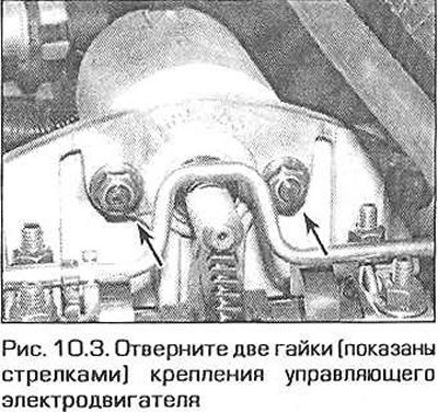
3. Turn off two nuts of fastening of the operating electric motor (pic. 10.3).
4. Turn the motor shaft clockwise by hand and pull it back at the same time. After removing the electric motor, remove the rubber seal - when installing, replace it with a new one.
5. When installing the motor, replace the seal and rotate the motor shaft counterclockwise to push it into place until the motor housing rests against the support bracket. Secure the motor with nuts and tighten them securely.
6. Replace the cylinder head cover (see paragraph 4).
Eccentric shaft
7. Remove the intake camshaft as directed in paragraph 11.
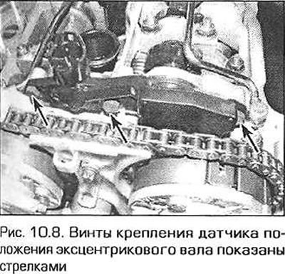
8. Turn out three bolts of fastening of the sensor of position of an eccentric shaft and remove the sensor (pic. 10.8).
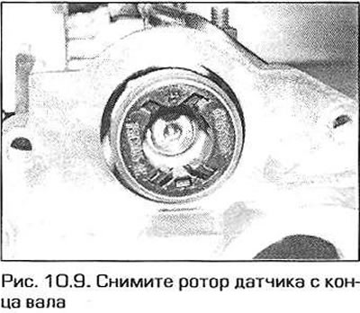
9. Remove the screws and remove the encoder rotor from the end of the shaft (pic. 10.9). The rotor is highly magnetized, store it in a plastic bag so that various metal objects are not attracted to it.
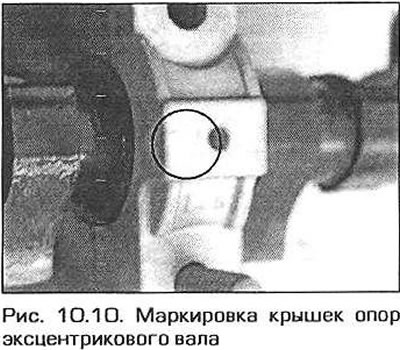
10. Unscrew the bolt of the fitting of the oil supply line, unscrew the nuts securing the covers of the shaft supports No. 2 and 4 and remove the oil supply pipe (pic. 10.10). The caps are numbered 1 to 4 starting from the timing chain side.
11. Turn away nuts of other covers and take an eccentric shaft from support.
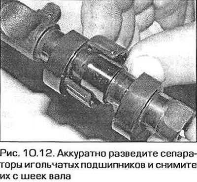
12. Carefully spread and remove the needle bearing cages from the shaft journals (pic. 10.12). Don't spread the separators too wide - they can be easily broken.
13. If necessary, remove the liners from the supports and covers.
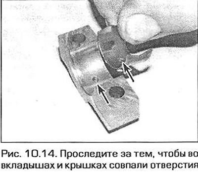
14. When assembling, insert new liners into the supports and covers. Make sure that the lubrication holes in the bushings and in the caps match (pic. 10.14).
15. Carefully spread the needle bearing cages and slide them over the shaft journals.
16. Lubricate bearings and liners with clean engine oil. Insert the eccentric shaft into the supports and install the covers in their original places. Fasten the No. 1 and No. 3 bearing caps with nuts by hand.
17. Reinstall the oil supply pipe and fasten by hand with the nuts of the covers of supports No. 2 and 4.
18. Install and securely tighten the oil inlet bolt.
19. Make sure that the support covers are installed correctly and in line, but do not completely tighten them yet.
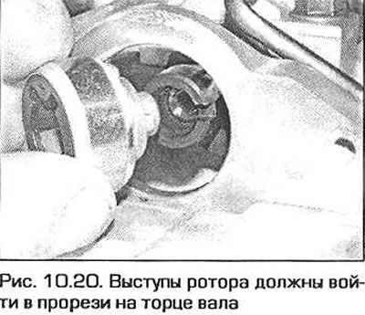
20. Install the sensor rotor on the end of the shaft, aligning the protrusions of the rotor with the slots on the end of the shaft (pic. 10.20). Screw in the non-magnetic screw and tighten it to the required torque.
21. Install the shaft position sensor and securely tighten it with the bolt.
22. The rest of the installation is carried out in the reverse order of removal.
Intermediate levers
23. Removal and installation of intermediate levers is described in paragraph 11 as part of the procedure for removing and installing the intake camshaft. When installing working levers, they should take their original places.
Electronic system control module
24. On left-hand drive models, remove the battery as directed in Chapter 5A. Under the battery, unscrew the four screws and remove the plate.
25. On right-hand drive models, the module is located in the left corner of the engine compartment, next to the wiring box. To remove the module from the bracket, pull its base away from the fender, then lift it up.
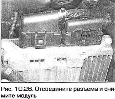
26. Disconnect the electrical connectors from the module and remove the module (pic. 10.26).
27. Installation is carried out in sequence. reverse withdrawal. Keep in mind that if a new module has been installed, then it must be coded using a special BMW tool. Contact your dealer or specialist.
Eccentric shaft position sensor
28. Remove the cylinder head cover (see paragraph 4).
29. Remove the three screws and remove the sensor (see fig. 10.8).
30. Installation is carried out in reverse order. Tighten the sensor screw securely.