
Table of contents: Engine M43TU ↓ Engine N42 ↓
- Home
- BMW 3 Series
- E46
- Power unit
- 4 cylinder engines
- Camshafts, rocker arms and hydraulic supports — removal and installation
Camshafts, rocker arms and hydraulic supports — removal and installation (BMW 3 Series E46)
Engine M43TU
Note. The manufacturer recommends compressing the valve springs before removing the camshafts to relieve the shafts from their pressure. This operation requires a special device. However, if you take precautions and unscrew the shaft support cap nuts gradually and evenly, you can do without a device. This is the method described below in this paragraph. When assembling, you will need new seals for the oil pipe mounting screws.
Removal
1. Remove the cylinder head cover (see paragraph 4).
2. Turn the crankshaft to the TDC position of piston No.1, but do not lock the crankshaft and camshaft in this position.
3. Turn the crankshaft one more revolution clockwise until piston No.4 is at TDC at the end of the compression stroke. Remove the two accessible camshaft sprocket mounting bolts.
4. Turn the crankshaft one revolution clockwise again to return piston No.1 to the TDC position. Secure the crankshaft and camshaft with the tools (see paragraph 3).
5. Remove the remaining two bolts securing the sprocket to the camshaft. Remove the shaft position sensor rotor from the sprocket.
6. Pull the top end of the tensioner shoe so that the chain is slack and the sprocket can be removed. Remove the sprocket and disconnect the chain from it. Do not let go of the chain so that it does not fall into the lower part of the housing. Tie the chain with wire somewhere at the top.
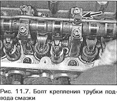
7. Unscrew the bolts securing the lubrication supply tube to the shaft support covers (Fig. 11.7). Remove the seals from the bolts.
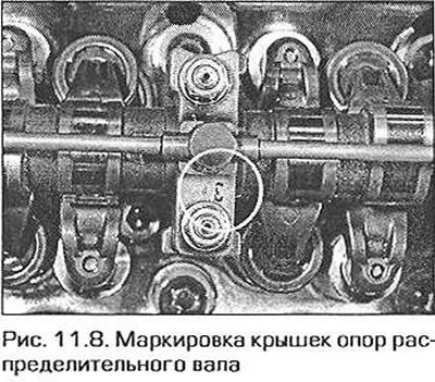
8. Check if the support caps are marked. The first cap should not be marked, but the others should be numbered from 2 to 5, starting from the chain side (Fig. 11.8). If there is no marking, apply it yourself.
9. Gradually and evenly unscrew the nuts securing the shaft support covers and remove the covers.
10. Lift the shaft from the supports and remove it from the cylinder head.
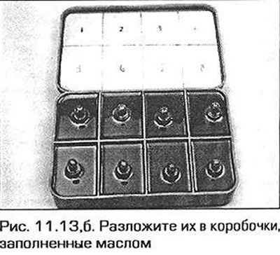
11. Have a box of sections filled with oil ready to hold the hydraulic rocker arm supports as they are removed, so that they are stored in the order they were originally installed.
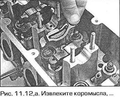
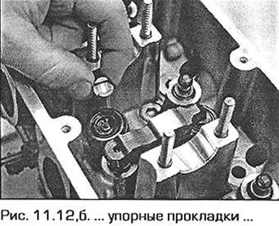
12. Remove the rocker arms, valve thrust washers and lay them out so that they can be installed in their original places during assembly (fig. 11.12.a, b).
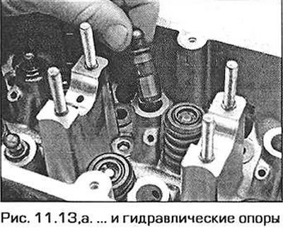
13. Remove the hydraulic rocker arm supports and place them in boxes filled with oil (fig. 11.13.a, b).
Inspection
14. Wash all parts, bearing bores in the cylinder head and covers. Carefully inspect the parts for wear and damage. Pay special attention to the condition of the cam surfaces and bearings. Inspect the rocker arms for wear and damage. Replace faulty parts.
Installation
15 Lubricate the bores for the hydraulic supports in the cylinder head and insert the supports into their original locations.
16. Place the thrust washers on the valve stems and install the rocker arms in their original positions.
17. Lubricate the shaft bearing bores in the cylinder head and lower the shaft into them so that both valves of cylinder #1 are closed and the valves of cylinder #4 are in the transition position (the exhaust valve closes and the intake valve opens). To check, look at the square flange at the end of the shaft - its flat faces should be perpendicular to the upper plane of the cylinder head (perpendicularity can be checked with a square). Additionally, the position of the camshaft can be checked using a template (see paragraph 3).
18. Lubricate the working surfaces of the support covers.
19. Install the covers in accordance with the marking. Screw on the cover fastening nuts and tighten them gradually one by one to the required torque.
20. Replace the seals on the oil supply tube mounting bolts, then install the tube and tighten the bolts.
21. Move the top side of the tensioner shoe away from the chain and loosen the chain enough to allow the sprocket to be installed on the camshaft. Engage the sprocket with the chain so that the arrow on the sprocket faces up.
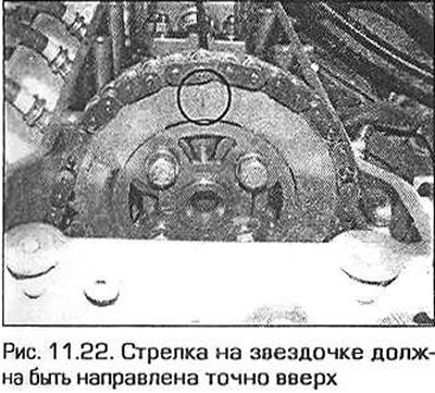
22. Fix the camshaft with a template (see paragraph 3). Place the sprocket on the shaft so that the bolt holes in the shaft flange align with the centers of the sprocket's oblong holes. Install the position sensor rotor on the sprocket so that the arrow on the rotor faces up (fig. 11.22). Install the two top sprocket mounting bolts and tighten them hand tight as much as possible.
23. Release the tensioner shoe and tighten the two accessible sprocket mounting bolts to the specified torque.
24. Remove the flywheel lock and camshaft position checking template.
25. Turn the crankshaft one full revolution clockwise until piston No.4 is at TDC at the end of the compression stroke. In this position, screw in and tighten the two remaining sprocket mounting bolts.
26. Install the cylinder head cover (see paragraph 4).
Engine N42
Removal the intake shaft
Note: Removing the shaft will require several BMW-specific tools.
27. Set the engine to the TDC position of piston N51, as specified in paragraph 3.
28. Having secured the camshafts as described in paragraph 3, loosen the bolts securing the valve timing adjustment units on both camshafts (see fig. 7.28).
29. On the front right side of the cylinder block, unscrew the tensioner plunger assembly (see fig. 7.29). Be prepared for oil to leak from the hole. The sealing washer under the head of the unit will need to be replaced with a new one during assembly. If the unit is to be used further, place it vertically and press on the plunger to force out any remaining oil from the unit.
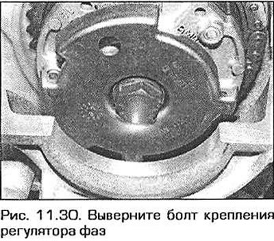
30. Completely unscrew the exhaust shaft phase adjuster mounting bolt and remove the adjuster together with the sprocket and the shaft position sensor rotor. Do the same with the intake shaft. Note that the adjusters are marked IN (intake) and EX (exhaust). Do not mix up the adjusters during assembly (fig. 11.30). When removing the sprocket, do not let go of the chain so that it does not fall into the lower part of the crankcase. Tie the chain somewhere at the top.
31. Remove the eccentric shaft motor as described in paragraph 10.
32. Disconnect the camshaft position sensor electrical connector on the front of the chain cover by squeezing the connector plug tabs.
33. Remove the plug behind the intake camshaft position sensor and unscrew the chain guide pin (see fig. 7.33).
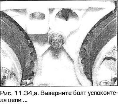
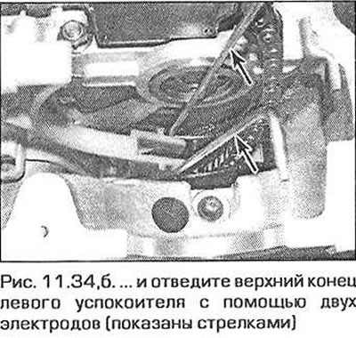
34. Loosen the chain guide bolt, carefully move the upper end of the left guide away and release the lower end of the upper guide. Remove the upper guide from the engine (fig. 11.34,a, b).
35. Unscrew the bolt of the oil supply pipe fitting to the exhaust camshaft and move the pipe back approximately 20 mm.
36. Remove the camshaft retaining templates.
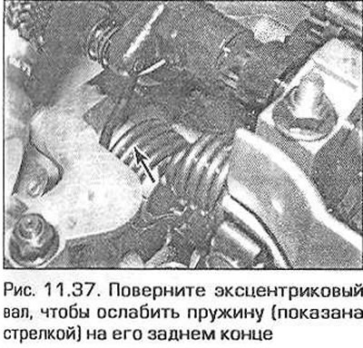
37. Turn the eccentric shaft with a hex key to loosen the spring at the rear end of the shaft as much as possible (fig. 11.37).
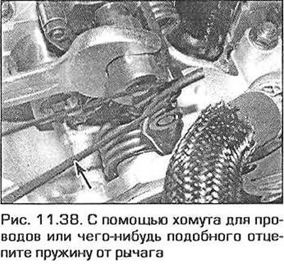
38. Using a wire tie or similar, pull the end of the spring up and back to release it from the lever and from the shaft (fig. 11.38).
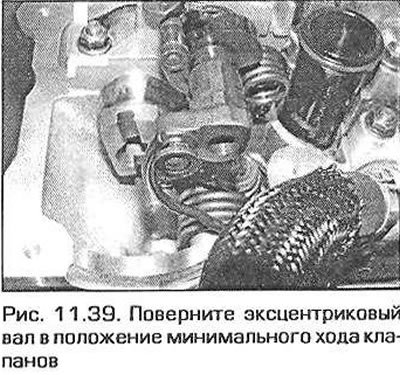
39. Turn the eccentric shaft to the minimum valve stroke position (fig. 11.39).
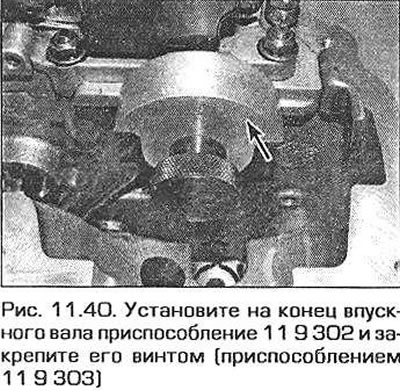
40. Install tool 11 9 302 on the end of the intake shaft and secure it with tool 11 9 303 (fig. 11.40). This way the shaft is fixed to the support.
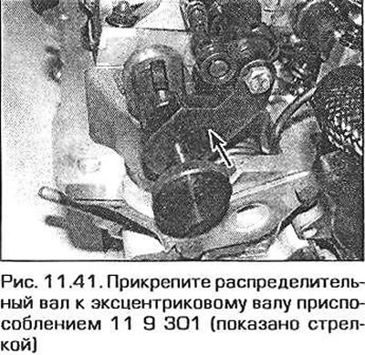
41. Attach the eccentric shaft to the rear end of the camshaft using tool 119 301 (fig. 11.41). Tighten the fixture screw by hand to prevent the camshaft from rotating.
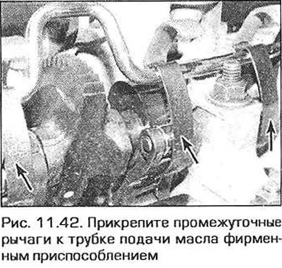
42. Attach tools 11 9 310 to the oil feed pipe and to the lower sides of the intermediate valve train levers to prevent the levers from moving (fig. 11.42).
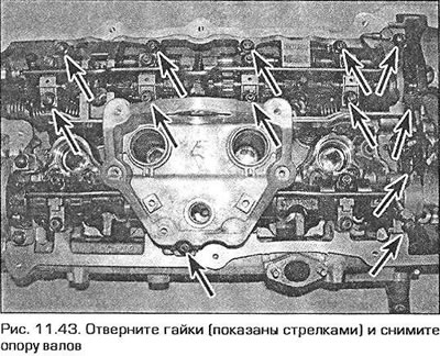
43. The shaft support is secured with 13 nuts. Gradually and evenly unscrew the nuts and remove the support (fig. 11.43).
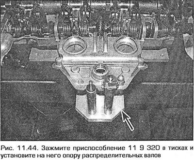
44. Before removing the camshaft, the pressure on the intermediate lever springs must be released. To do this, use tools 11 9 390 and 11 9 320 as follows. Clamp tool 11 9 320 in a vice. Turn the shaft support over and install it on the tool (fig. 11.44).
45. Pull the spark plug sealing tubes out of the support. Discard the tube sealing rings - new ones will be required for installation.
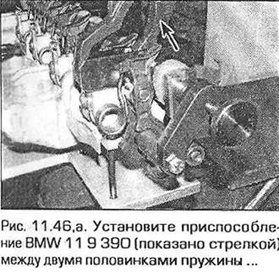
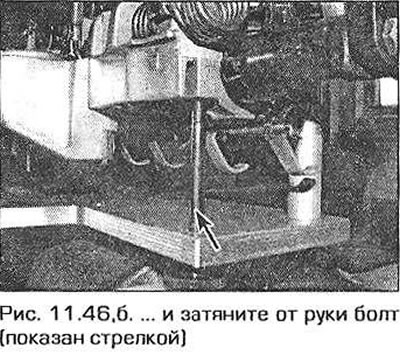
46. Fit tool 11 9 390 over the camshaft between the two halves of the N5 cylinder spring 4. Secure the tool with the bolt supplied (fig. 11.46,a, b).
47. Secure the fixture so that its collar is located on top of the spring mounting plate. Squeeze the jaws of the fixture. Unscrew the plate mounting screw and slowly release the jaws, releasing the spring (fig. 11.47,a,b).
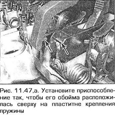
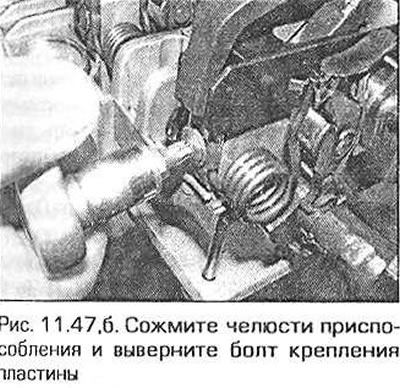
Warning! Do not attempt to release the springs without the specified tool. The springs are tight and may cause injury.
48. Remove the spring together with the plate.
49. Remove the tool and repeat the procedure on the remaining springs.
50. Remove the devices that attach the intermediate levers to the lubrication supply pipe. Remove the intermediate levers and store them in a certain order. When installing, they must take their previous position.
51. Remove the tools from both ends of the camshaft. Remove the camshaft.
52. If necessary, remove the rocker arms and hydraulic supports of the intake valves. Store the rocker arms in a certain order - they must take their previous position during assembly. Disconnect the rocker arms from the hydraulic supports. The supports must also be installed in their previous places during assembly. Store the supports immersed in engine oil.
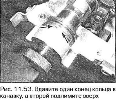
53. If necessary, you can remove the spring rings on the ends of the shafts. To do this, press one end of the ring into the groove 8, and pull the ring out by the other end (fig. 11.53). Be careful - the rings are fragile and can easily break.
Inspection of the intake shaft
54. Wash all parts, as well as the working surfaces of the bearings and shaft covers. Inspect the parts for wear and damage. Pay special attention to the surfaces of the bearings and cams. Inspect the surfaces of the rocker arms and intermediate levers. Replace heavily worn and damaged parts.
Installing the intake shaft
55. Turn the shaft support over and install it on the device 11 9 320, clamped in a vice. Lubricate the working surfaces of the shaft supports with engine oil.
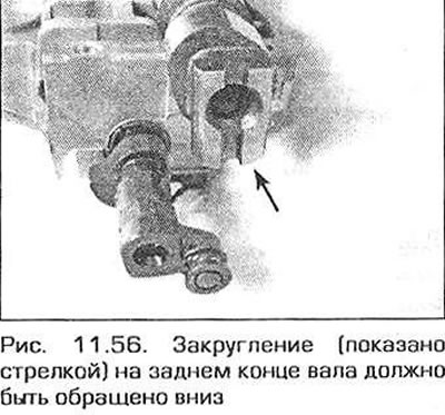
56. Place the intake shaft in the supports. Turn the shaft so that the rounding at its rear end is facing downwards (fig. 11.56).
57. Turn the spring rings on the front end of the shaft with the gap facing up (see fig. 11.53).
58. Fit tools 119 302 and 11 9 303 to the front end of the shaft and tool 11 9 301 to the rear end. Fitting these tools secures the shaft to the support and to the eccentric shaft. Check that the eccentric shaft is fitted correctly.
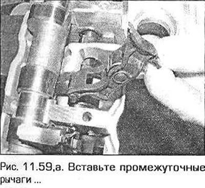
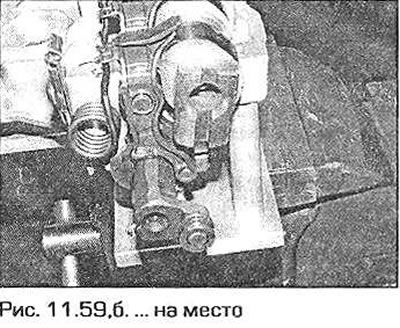
59. Lubricate the working surfaces of the intermediate levers, then insert them into place between the camshaft and eccentric shafts (fig. 11.59,a,b).
60. Secure the intermediate levers with tools 11 9 310 to the lubrication supply pipe.
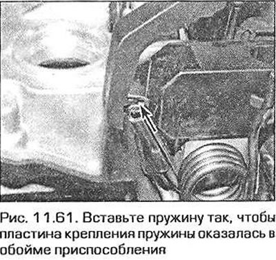
61. As with disassembly, fit tool 11 9 390 in the gap where the intermediate lever springs are to be inserted. Start at the rear end of the shaft. Insert the spring so that the spring mounting plate is in the tool holder (rice, 11.61).
62. Carefully close the jaws of the device and secure the spring mounting plate with the screw. Tighten the screw securely. Repeat the above steps for the remaining springs.
63. Place new sealing rings on the spark plug tubes (a ring of smaller diameter is installed on the lower end of the tube, see Fig. 4.25). Lubricate the rings with clean engine oil and insert the tubes into the cylinder head.
64. Install the intake rocker arms (if they were removed) to their former places.
65. Install the support with shafts on the cylinder head and secure with 13 nuts by hand.
66. In sequence from the inside out, tighten the shaft support nuts first to 5 Nm, then in the same sequence to 10 Nm. If the eccentric shaft was previously removed, now is the time to finally tighten the covers of its supports to the required torque.
67. Remove the devices that secure the intermediate levers to the tube and secure the camshaft. Replace the lubrication supply tube to the exhaust shaft, screw in and tighten the tube union bolt.
68. Using a hex key, turn the eccentric shaft so that it becomes possible to install a spring on its rear end. By turning the shaft, achieve maximum spring force.
69. Install the devices that fix the camshafts in the TDC position of piston No.1.
70. Otherwise, installation is carried out in the reverse order of removal.
Removal the exhaust shaft
71. Remove the support with shafts as indicated in paragraphs 27-43 of this section.
72. Remove the three bolts and vacuum pump from the rear end of the exhaust shaft (see chapter 9). The sealing ring can be discarded - a new one will be required during installation.
73. Remove the lubrication supply tube to the outlet shaft from the clamps on the bearing covers.
74. Gradually and evenly unscrew the nuts of the exhaust shaft support covers. Pay attention to the marking of the covers: they should be numbered A1, A2, A3 and A4 from the intake shaft side. The numbering starts from the chain side. Remove the covers.
75. Lift the exhaust shaft out of its supports. If necessary, remove the spring rings from the end of the shaft as described in step 53. Be careful - the rings break easily.
76. If necessary, remove the exhaust rocker arms together with the hydraulic supports. Separate the supports from the rocker arms. Store them so that they take their original places during assembly. Store the hydraulic supports immersed in engine oil.
Inspection of the exhaust shaft
77. See paragraph 54.
Installing the exhaust shaft
78. Lubricate the working surfaces of the shaft supports with engine oil.
79. Install the exhaust rocker arms (if they were removed).
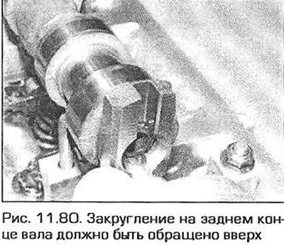
80. Place the shaft in the supports and turn it so that the rounding at the rear end of the shaft faces upwards (fig. 11.80).
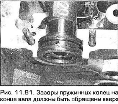
81. Turn the rings on the front end of the shaft with the gaps facing up (fig. 11.81).
82. Lubricate the shaft support covers with engine oil and install the covers in place, taking into account the markings.
83. Install the oil feed pipe clamps on covers No.1 and 4. Screw on the cover nuts and tighten them evenly and gradually until the lower surfaces of the covers touch the cylinder head.
84. In sequence from the inside out, tighten the cap nuts one-half turn at a time until the required torque is reached.
85. Secure the grease supply tube in the clamps and move the tube back approximately 20 mm.
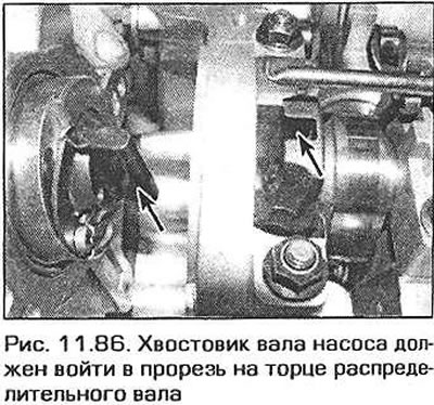
86. Install the vacuum pump in place, aligning the pump shaft end with the slot on the end of the camshaft (fig. 11.86).
87. Otherwise, installation is carried out in the reverse order of removal.
This article is available at russian, bulgarian, belarusian, ukrainian, serbian, croatian, romanian, polish, slovak, hungarian
Article verified: Ilyinsky Matvey
Share information:
Previous articles
БМВ E46: 4 cylinder engines
Next articles
Similar articles on other types of BMW cars:
Removal and installation rocker arms and rocker shafts BMW 5 Series E34 (1988-1996)
Inspection, removal, installation and replacement of suspension arm… BMW 5 Series E28 (1981-1988)
Removal and installation of cylinder heads, camshafts and their… BMW 7 Series E38 (1994-2001)
Cylinder Head Cover — Removal and Installation BMW 7 Series E32 (1986-1994)
Pistons — removal and installation BMW X3 E83 (2003-2010)
Removal and installation the engine BMW X5 E53 (1999-2006)
Link in different formats to this page
Visitor comments
No comments yet
- General information
- Manual
- Maintenance
- Power unit
- Engine repair
- Cooling system
- Power system (gasoline)
- Injection system (gasoline)
- Fuel system (diesel)
- Exhaust system
- Ignition system
- Charge and launch systems
- Transmission
- Car gearbox
- Clutch and drive shafts
- Chassis
- Brake system
- Suspension front and rear
- Steering
- Body
- Body care and repair
- Exterior
- Interior
- Electrical equipment
- Troubleshooting
- Lighting and signaling
- Equipment and devices
- Heater and air conditioner
- Electrical circuits
- General information
- Manual
- Repair on the road
- Weekly checks
- Maintenance
- Troubleshooting
- Power unit
- 4 cylinder engines
- 6 cylinder engines
- Engine overhaul
- Cooling and heating
- Fuel and exhaust system
- Starting and charging system
- Ignition system
- Transmission
- Clutch
- Mechanical gearbox
- Automatic gearbox
- Cardan and drive shafts
- Chassis
- Brake system
- Wheel suspension
- Steering
- Body
- Exterior
- Interior
- Electrical equipment
- Equipment and devices
- Electrical circuits
- General information
- Maintenance
- Power unit
- Engine repair
- Cooling system
- Ignition system
- Supply system
- Fuel injection system
- Exhaust system
- Transmission
- Clutch
- Car gearbox
- Front and rear axle
- Chassis
- Steering
- Brake system
- Body
- Exterior
- Interior
- Electrical equipment
- Heating system
- Equipment and devices
- Power devices
- Electrical circuits
- Power unit
- M10/M20 engine
- M40 engine
- Ignition system
- Lubrication system
- Cooling system
- Supply system
- Fuel injection
- Exhaust system
- Transmission
- Clutch
- Manual gearbox
- Front axle
- Rear axle
- Chassis
- Steering
- Brake system
- Body
- Exterior
- Interior
- Electrical equipment
- Heating system
- Equipment and devices
- Electrical circuits
- General information
- Specifications
- Operation and maintenance
- 4-cylinder engine
- Engine repair
- Cooling and lubrication system
- Supply system
- Ignition system
- 6-cylinder engine
- Engine repair
- Cooling and lubrication system
- Supply system
- Fuel injection system
- Ignition system
- Transmission
- Clutch
- 4-speed manual gearbox
- 5-speed manual gearbox
- Automatic gearbox
- Cardan and rear axle
- Chassis
- Steering
- Front suspension
- Rear suspension
- Brake system
- Electrical equipment
- Equipment and devices
- Electrical circuits