
General information
1. To compensate for unbalanced engine sip and eliminate vibration during its operation, N42 4-cylinder engines are equipped with two balance shafts with counterweights at the ends. The shafts rotate in opposite directions and are driven by a chain from the crankshaft sprocket. The shafts are part of a common assembly with the oil pump, so the details of the removal and installation of the balancing shafts are described in paragraph 17 as part of the removal and installation of the oil pump.
2. M43Ti engines are also equipped with breading shafts, but they are also gear driven from the crankshaft. Unlike the N42 engine, the balance shafts can be removed and installed independently of the oil pump. Therefore, the following description only applies to the M43TU engine.
Withdrawal (M43TU engines only)
3. Remove the oil pan as described in paragraph 1 3.
4. Rotate the engine crankshaft until pistons #1 and #4 are at TDC. Lock this position by inserting the rod into the engine flywheel (see paragraph 3).
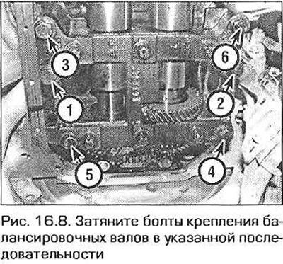
5. In the reverse order to that shown in fig. 16.8, turn out bolts of fastening of the case of balancing shafts. Remove the housing together with the shafts. Keep in mind that the case is heavy. Remove the gasket between the shaft housing and the cylinder block.
Installation (engine M43TU)
6. Make sure the shaft housing dowel pins are in place in the cylinder block. Lay spacers on them. Note If the cylinder block, crankshaft or balancing shaft housing has been replaced, then during installation it will be necessary to check and adjust the clearance in the meshing of the shaft drive gears. To prevent breakage at the beginning of this procedure, install the thickest gasket first (2.25mm).
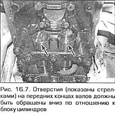
7. Rotate the balance shafts so that the holes on the front ends of the shaft8 face down (into position "6 o'clock' in relation to the cylinder block) (pic. 16.7).
8. Install the shaft housing on the pins and screw in the bolts. If the engagement gap requires adjustment (see previous point), reinstall the old bolts as the housing may need to be removed and reinstalled to replace the spacers. If it is not necessary to adjust the engagement, screw in new bolts immediately. Tighten the bolts to the required torque in the sequence shown in fig. 16.8.
9. To measure the clearance in the meshing of the shaft drive gears, install a dial indicator and press its feeler against the side surface of the driven gear tooth. Rotate the gear to one side to select the mesh clearance and reset the indicator. Rotate the driven gear the other way to select the gap again and read the gauge reading. Remove the fixing rod from the flywheel, turn the crankshaft 120°and measure the clearance again. Then do the same by turning the crankshaft 240°. Find the average gap value by adding all three readings and dividing the sum by three. Compare the value obtained with the Technical data. If the gap requires adjustment, replace the spacer under the shaft housing. Decreasing the shim thickness by 0.03mm reduces the engagement clearance by 0.02mm. Keep in mind that the shims under both sides of the shaft housing must be the same thickness. At the end of the adjustment, tighten the shaft housing mounting bolts to the required torque. 10 Install the oil pan as described in paragraph 13.