
Table of contents: Engine N43TU ↓ Engine N42 ↓
- Home
- BMW 3 Series
- E46
- Power unit
- 4 cylinder engines
- Oil pump — removal, inspection and installation
Oil pump — removal, inspection and installation (BMW 3 Series E46)
Engine N43TU
Removal
1. The oil pump is a single structure with the chain housing.
2. Remove the chain housing as described in paragraph 9.
Inspection
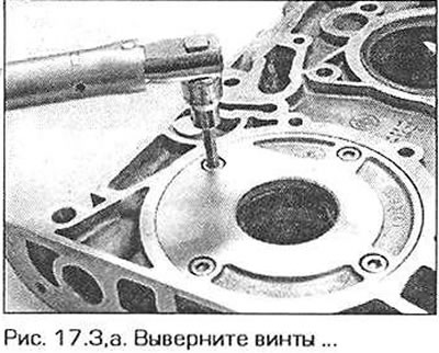
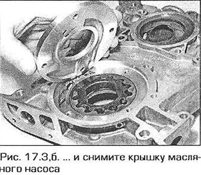
3. On the back of the chain housing, unscrew the screws and remove the oil pump cover to gain access to its rotors (fig. 17.3.a, b).
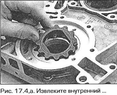
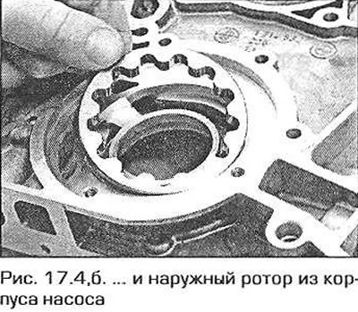
4. Check if there is a marking on the upper ends of the rotors for their correct mutual arrangement. If there is no such marking, apply it yourself. Remove the rotors from the housing (fig. 17.4,a,b).
5. Clean the pump housing and rotors thoroughly, then reinsert the rotors into the housing, observing the markings.
6. Using flat feeler gauges, measure the clearance between bore 8 of the pump body and the outer rotor (Fig. 17.6). Place the edge of a steel ruler on the end of the pump body and using flat feeler gauges, measure the axial clearances between the rotor surfaces and the pump plane.
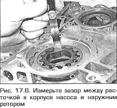
7. If the gap is too large, consult your BMW dealer about replacing the parts or the pump assembly.
8. If the clearances are normal, remove the rotors, pour some engine oil into the housing, then insert and turn the rotors to lubricate all contact parts of the pump.
9. Install the pump cover and tighten the screws to the required torque.
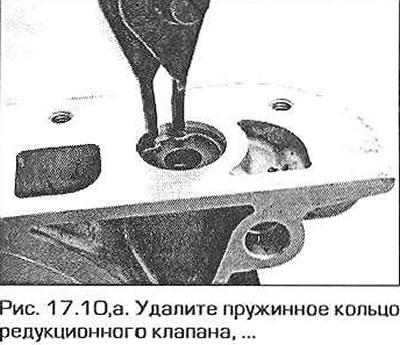
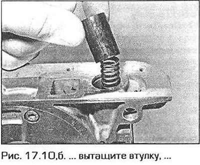
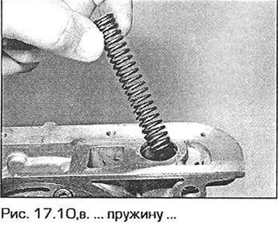
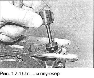
10. To check the pressure reducing valve, remove the spring ring from the valve body, remove the bushing, spring and plunger. Since the manufacturer does not regulate the length of the valve spring in a free state, compare its length with a new spring (fig. 17.10,a-g).
11. Assemble the valve in reverse order.
Installation
12. Install the chain housing onto the engine as described in paragraph 9.
Engine N42
Removal
13. On these engines, the oil pump is structurally integrated with the balance shaft housing. It is impossible to separate the pump from the shafts. Remove the oil pan as described in paragraph 13.
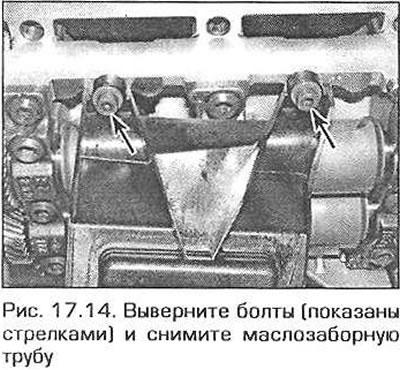
14. Unscrew the two bolts securing the oil intake pipe. Unscrew the pipe from the pump and pull it down (rice: 17.14).
15. Turn the crankshaft to the TDC position of piston No.1 (see paragraph 3). Lock the flywheel in this position.
16. Unscrew the oil pump sprocket fastening nut. Caution! The nut has a left-hand thread.
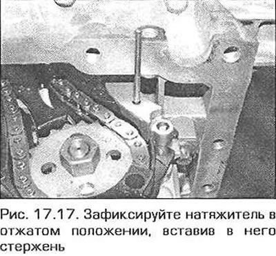
17. Press the pump drive chain tensioner and fix it in the pressed position by inserting a rod of a suitable diameter into the tensioner hole (fig. 17.17).
18. Unscrew the bolts securing the lower chain guide to the oil pump housing and balance shafts.
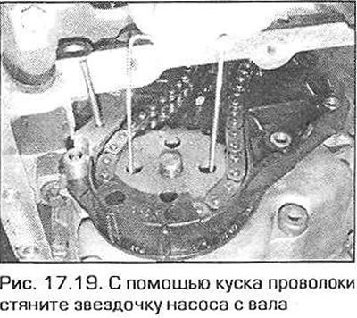
19. Use a piece of wire to pull the sprocket off the oil pump shaft (fig. 17.19).
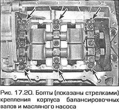
20. Ask an assistant to hold the case and unscrew the 8 bolts. Lightly press the case down from behind, then pull it back (fig. 17.20). After removing the unit, remove the damper from the mounting pins. It is not recommended to disassemble the unit.
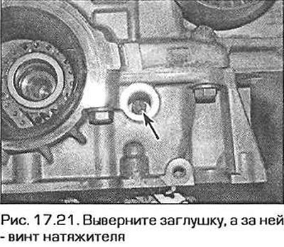
21. To replace the oil pump drive chain, remove the timing chain as described in paragraph 7. Unscrew the plug on the right side of the crankshaft and unscrew the screw securing the upper part of the oil pump drive chain tensioner (fig. 17.21).
22. Pull the tensioner with the damper down. The tensioner can be separated from the damper only after they have been removed.
Installation
23. Place the pump drive chain on the crankshaft sprocket (if the chain was removed before). Install the timing chain (see paragraph 7).
24. Install the tensioner and chain guide of the oil pump. Screw in the tensioner mounting screw and tighten it by hand for now.
25. Make sure that the balancing shaft housing dowel pins are in place. Insert the pump and balancing shaft drive shaft into the sprocket and install the housing, aligning the dowel pins with the holes. Lubricate the threads of the mounting bolts and screw them into the corresponding holes. Tighten the bolts to the specified torque.
26. Use a piece of wire to pull the sprocket off the oil pump shaft (see fig. 17.19).
27. Use two straight metal strips to align the flats of the balancing shafts and secure them in this position with a clamp (see Fig. 7.49.a, b). Keep in mind that the wider slots on the ends of the balance shafts should be at the top (closer to the root supports).
28. Make sure that the crankshaft is locked in the installation position. Put the sprocket on the shaft splines. Pull out the rod that locks the chain tensioner and check the position of the balance shafts again. If the shafts are out of position or the sprocket splines do not match the shaft splines, turn the balance shafts 360° and try again. It is possible that you will not be able to put the sprocket on the first or even the second time.
29. Once the shafts are aligned and the sprocket is on the splines, install the tensioner/damper mounting screws and tighten them securely. Screw in the plug.
30. Screw on the sprocket mounting nut and tighten it to the required torque.
Attention! The nut has a left-hand thread.
31. Install the oil pickup pipe, replacing the sealing ring on it. Securely tighten the pipe mounting bolt.
32. Remove the crankshaft lock. Install the oil pan.
This article is available at russian, bulgarian, belarusian, ukrainian, serbian, croatian, romanian, polish, slovak, hungarian
Article verified: Ilyinsky Matvey
Share information:
Previous articles
БМВ E46: 4 cylinder engines
Next articles
Similar articles on other types of BMW cars:
Removal, inspection and installation of the oil pump BMW 5 Series E28 (1981-1988)
Removal and installation the oil pump BMW 5 Series E12 (1972-1981)
Oil pump — removal, inspection and installation BMW 7 Series E32 (1986-1994)
Removal and installation the oil pump BMW 7 Series E38 (1994-2001)
Pistons — removal and installation BMW X3 E83 (2003-2010)
Removal and installation the engine BMW X5 E53 (1999-2006)
Link in different formats to this page
Visitor comments
No comments yet
- General information
- Manual
- Maintenance
- Power unit
- Engine repair
- Cooling system
- Power system (gasoline)
- Injection system (gasoline)
- Fuel system (diesel)
- Exhaust system
- Ignition system
- Charge and launch systems
- Transmission
- Car gearbox
- Clutch and drive shafts
- Chassis
- Brake system
- Suspension front and rear
- Steering
- Body
- Body care and repair
- Exterior
- Interior
- Electrical equipment
- Troubleshooting
- Lighting and signaling
- Equipment and devices
- Heater and air conditioner
- Electrical circuits
- General information
- Manual
- Repair on the road
- Weekly checks
- Maintenance
- Troubleshooting
- Power unit
- 4 cylinder engines
- 6 cylinder engines
- Engine overhaul
- Cooling and heating
- Fuel and exhaust system
- Starting and charging system
- Ignition system
- Transmission
- Clutch
- Mechanical gearbox
- Automatic gearbox
- Cardan and drive shafts
- Chassis
- Brake system
- Wheel suspension
- Steering
- Body
- Exterior
- Interior
- Electrical equipment
- Equipment and devices
- Electrical circuits
- General information
- Maintenance
- Power unit
- Engine repair
- Cooling system
- Ignition system
- Supply system
- Fuel injection system
- Exhaust system
- Transmission
- Clutch
- Car gearbox
- Front and rear axle
- Chassis
- Steering
- Brake system
- Body
- Exterior
- Interior
- Electrical equipment
- Heating system
- Equipment and devices
- Power devices
- Electrical circuits
- Power unit
- M10/M20 engine
- M40 engine
- Ignition system
- Lubrication system
- Cooling system
- Supply system
- Fuel injection
- Exhaust system
- Transmission
- Clutch
- Manual gearbox
- Front axle
- Rear axle
- Chassis
- Steering
- Brake system
- Body
- Exterior
- Interior
- Electrical equipment
- Heating system
- Equipment and devices
- Electrical circuits
- General information
- Specifications
- Operation and maintenance
- 4-cylinder engine
- Engine repair
- Cooling and lubrication system
- Supply system
- Ignition system
- 6-cylinder engine
- Engine repair
- Cooling and lubrication system
- Supply system
- Fuel injection system
- Ignition system
- Transmission
- Clutch
- 4-speed manual gearbox
- 5-speed manual gearbox
- Automatic gearbox
- Cardan and rear axle
- Chassis
- Steering
- Front suspension
- Rear suspension
- Brake system
- Electrical equipment
- Equipment and devices
- Electrical circuits