
Table of contents: Engine M43TU ↓ Engine N42 ↓
- Home
- BMW 3 Series
- E46
- Power unit
- 4 cylinder engines
- Cylinder head — removal, inspection and installation
Cylinder head — removal, inspection and installation (BMW 3 Series E46)
Note: New bolts and a new gasket will be required for installation.
Engine M43TU
Removal
1. Relieve the fuel system pressure as described in Chapter 4A. Disconnect the negative battery terminal.
2. Drain the coolant as directed in chapter 1.
3. Remove the air cleaner and air flow sensor as described in paragraph 12 of chapter 4A.
4. Remove the upper and lower sections of the intake manifold as shown in chapter 4A.
5. Disconnect the exhaust manifold from the exhaust pipe as shown in chapter 4A.
6. Disconnect the coolant hose from the cylinder head.
7. Remove the upper chain cover as shown in paragraph 6 this chapter.
8. Remove the ignition coils as described in eye 5B.
9. Remove the spark plugs (see chapter 1).
10. Disconnect the electrical connectors from the coolant temperature sensors on the left side of the cylinder head.
11. Disconnect the heater hoses and valve at the engine bulkhead.
12. Turn the crankshaft to the TDC position of piston No.1 (see paragraph 3) and fix it in this position.
13. Unscrew the camshaft sprocket mounting bolts and remove the camshaft position sensor rotor.
14. Pull back the top end of the chain tensioner shoe. Loosen the chain enough to allow the sprocket to be removed. Remove the sprocket from the shaft and unhook it. Do not let go of the chain to prevent it from falling into the engine. Tie the top of the chain to something.
15. Unscrew the bolts securing the tensioner shoe and chain guide to the cylinder head.
Attention! To prevent the valves from hitting the pistons when installing the cylinder head, it is necessary to ensure that the crankshaft is in such a position that all the pistons are in the middle of the cylinders. Therefore, before continuing disassembly, remove the retainer from the flywheel and turn the crankshaft 45° counterclockwise.
16. Check that all hoses and wires are removed from the cylinder head and that nothing is interfering with its removal.
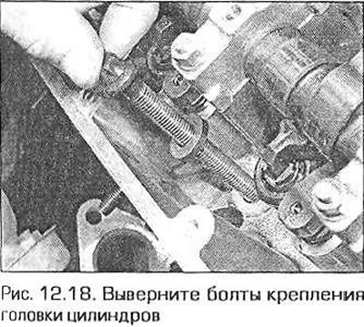
17. Gradually loosen the cylinder head bolts in a spiral sequence.
18. Remove the bolts (fig. 12.18).
19. Rock the cylinder head and separate it from the block. Do not press the head from the block with any tool - this can damage their mating surfaces.
20. Ideally, you will need two assistants to remove the head. Have one assistant hold the chain, preventing it from falling through. And with the help of the second assistant, lift the head off the block. Tie the chain with wire somewhere on top.
21. Remove the head gasket and rubber seals from the upper ends of the chain housing and lower chain cover.
Inspection
22. Disassembly and assembly of the cylinder head is described in detail in Chapter 2B.
23. The mating surfaces of the cylinder head and block must be thoroughly cleaned. Use a scraper to remove carbon deposits and remnants of the old gasket. Clean the piston crowns as well. Use the scraper with caution - aluminum parts are easy to scratch. Make sure that dirt does not get into the engine's oil and water channels. Seal the channels with tape. To prevent scraped-off carbon deposits from getting into the gaps between the pistons and cylinders, coat these gaps with consistent grease. After cleaning each piston, turn the crankshaft so that the piston goes down and wipe the grease along with the remaining carbon deposits from the cylinder surfaces with a clean rag.
24. Inspect the mating surfaces of the head and block for nicks, deep scratches, and other damage. Minor defects can be removed with a fine file. More serious damage can sometimes be removed by machine processing, but this is a job for a specialist.
25. If there is a suspicion that the head is warped, place the edge of a steel ruler on the surface of the head and check with a flat feeler gauge for a gap between the head and the ruler (see chapter 2B).
26. Clean the bolt holes in the block by wrapping a rag around a screwdriver. Remove moisture and oil from the holes, otherwise, when tightening the bolts, hydraulic pressure may be created on them, which can tear the block.
27. Check the condition of the threads in the holes. Run the threads with a tap of the required size.
Installation
28. Make sure that the mating surfaces of the head and block are sterilely clean, that no liquid or oil remains in the bolt holes, that the threads of the holes in the block are not damaged and that the bolts can be easily screwed in and out.
29. Ensure that all locating pins and adapter tubes are in place in the block.
Caution! To prevent the valves from hitting the pistons when installing the cylinder head, it is necessary to ensure that the crankshaft is in such a position that all the pistons are in the middle of the cylinders. Therefore, before continuing, turn the crankshaft to the TDC position of piston No.1, then turn the crankshaft 45° counterclockwise.
30. Place a new gasket on the block surface with the right side up. Keep in mind that if the head surface has been ground, a repair size gasket is available for such cases, 0.3 mm thicker than the standard one.
31. Place the new seal on the top end of the chain housing. Do not place the new seal on the bottom chain cover yet.
32. Install a reference template on the camshaft to ensure that the shaft is in the TDC position of piston No.1.
33. Place the head on the block. Move the chain tensioner shoe as needed so that it does not interfere with lowering the head. Make sure that all the pins are in their holes.
34. Install the new head bolts. Screw the bolts in as tight as possible by hand.
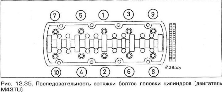
35. Tighten the bolts in the sequence shown in Fig. 12.35 as specified in the Technical Data, i.e. tighten all the bolts to the 1st stage torque, then tighten them to the required angle in the same sequence, etc.
36. Screw the tensioner shoe and chain guide mounting bolts into the head.
37. Turn the crankshaft 45° clockwise so that it again reaches the TDC position of piston No.1. Fix the engine shafts in this position by inserting a locking pin into the flywheel and installing a template for checking the position of the camshaft (see paragraph 3).
38. Pull back the chain tensioner shoe to allow the camshaft sprocket to be installed. Insert the sprocket into the chain with the arrow on the sprocket facing up.
39. Install the sprocket on the camshaft, aligning the holes in the shaft flange with the centers of the elongated holes in the sprocket (the camshaft must be fixed with a template). Install the shaft position sensor rotor onto the sprocket so that the arrow on it faces upward. Screw in the sprocket mounting bolts and tighten them by hand.
40. Release the tensioner shoe, then tighten the sprocket bolts to the specified torque.
41. Remove the retainer from the flywheel and remove the template from the camshaft.
42. Otherwise, installation is carried out in the reverse order of removal, taking into account the following notes.
- a) Route and connect all hoses and wires in the same way as before disassembly.
- b) Install both sections of the intake manifold as described in Chapter 4A.
- c) Install the air cleaner and air flow sensor as described in Chapter 4A.
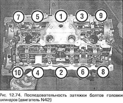
- d) Connect the exhaust manifold to the exhaust pipe.
- d) Screw in the spark plugs as described in Chapter 7.
- e) Install the upper chain cover as described in paragraph 6.
- g) Finally, fill the cooling system (see chapter 1) and the fuel system (see chapter 4A).
Engine N42
Removal
43. Drain the coolant as directed in chapter 1.
44. Set the engine to the TDC position of piston No.1, as indicated in paragraph 3.
45. Fix the camshafts as described in paragraph 3, loosen the camshaft phase adjuster mounting bolts (see fig. 11.28).
46. On the front right side of the cylinder block, unscrew the tensioner plunger assembly (see fig. 11.29). Be prepared for oil to leak from the hole. The sealing washer can be discarded - a new one will be needed for assembly. If the unit is to be used further, stand it upright, press the plunger and squeeze the remaining oil out of the unit.
47. Finally, unscrew the exhaust camshaft phase adjuster mounting bolt and remove the adjuster together with the shaft position sensor rotor and sprocket (see fig. 11.30). Do the same with the intake shaft. The regulators are marked IN (intake) and EX (exhaust). Do not mix them up when assembling. Keep the chain taut - do not let it fall inside the engine. Tie it with a piece of wire somewhere on top.
48. Remove the intake and exhaust manifolds (see chapter 4).
49. Remove the eccentric shaft motor as shown in paragraph 10.
50. On the chain cover, disconnect the electrical connector of the intake camshaft position sensor. To do this, squeeze the tabs of the connector plug.
51. Remove the plug behind the intake camshaft position sensor and unscrew the chain guide pin (see fig. 7.33). Be careful not to drop your finger inside the engine.
52. Loosen the chain guide bolt, carefully move the upper end of the left guide away and release the lower end of the upper guide. Remove the upper guide from the engine (see Fig. 11.34, a, b),
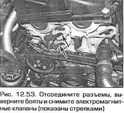
53. At the front of the engine, disconnect the electrical connectors of the solenoid valves, unscrew the bracket mounting screws and remove the solenoid valves from the engine (fig. 12.53).
54. Remove the plug from the left side of the chain cover (behind the rigging eye) and turn out the upper pin of the left chain guide (see fig. 7.36).
55. Remove the locking templates from the camshafts.
56. Disconnect all electrical connectors on the cylinder head and remove the wires. Note the routing of the wires and the position of the connectors.
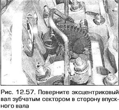
57. Turn the eccentric shaft by the hexagon on it so that its toothed sector turns towards the intake shaft (fig. 12.57). In this position, access to the bolts on the inlet side of the cylinder head is provided.
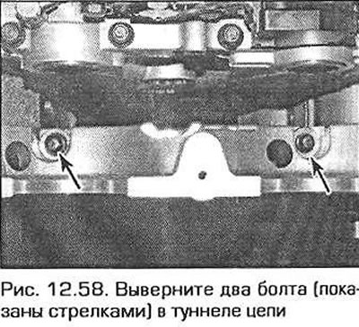
58. Remove the two bolts in the chain tunnel that secure the head to the cylinder block (fig. 12.58).
59. Remove the plug from the eccentric shaft control motor support bracket.
60. In the reverse order to that shown in Fig. 12.74, gradually and evenly loosen and remove the cylinder head bolts. Bolts 7 through 10 have an M8 thread and an E10 head, while bolts 1 through 6 have an M10 thread and an E12 head. Note that the bolt in position 10 is shorter than the others.
61. Separate the head from the block by rocking it from side to side. Do not press the head from the block with any tool - this can easily damage the mating surfaces.
62. Ideally, you will need two assistants to remove the head. Have one assistant hold the chain, preventing it from falling through, and with the help of the second assistant, lift the head off the block. Tie the chain with wire somewhere on top.
63. Remove the gasket from under the head.
Inspection
64. The mating surfaces of the cylinder head and block must be thoroughly cleaned. Use a scraper to remove carbon deposits and remnants of the old gasket. Clean the piston crowns as well. Use the scraper with caution - aluminum parts are easy to scratch. Make sure that dirt does not get into the engine's oil and water channels. Seal the channels with tape. To prevent scraped-off carbon deposits from getting into the gaps between the pistons and cylinders, coat these gaps with consistent grease. After cleaning each piston, turn the crankshaft so that the piston goes down and wipe off the grease along with the remaining carbon deposits from the cylinder surfaces with a clean rag.
65. Inspect the mating surfaces of the head and block for nicks, deep scratches, and other damage. Minor defects can be removed with a fine file. More serious damage can sometimes be removed by machine processing, but this is a job for a specialist.
66. If there is a suspicion of warping of the head, place the edge of a steel ruler on the surface of the head and check with a flat feeler gauge for a gap between the head and the ruler (see chapter 2B).
67. Clean the bolt holes in the block by wrapping a rag around a screwdriver. Remove moisture and oil from the holes, otherwise, when tightening the bolts, hydraulic pressure may build up underneath them, which can tear the block apart.
68. Check the condition of the threads in the holes. Run the threads with a tap of the required size.
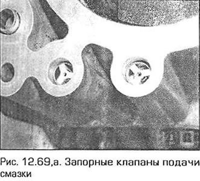
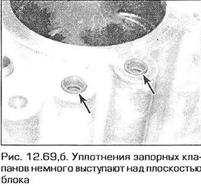
69. On the front side of the cylinder block there are shut-off valves for supplying lubricant to the intake and exhaust camshafts with rubber seals. If the valves are heavily soiled or covered with deposits, remove the seals and valves and replace them with new ones. When installed correctly, the ends of the rubber seals should protrude slightly above the mating surface of the block with the head (fig. 12.69, a, b).
Installation
70. Make sure that the mating surfaces of the head and block are sterilely clean, that no liquid or oil remains in the bolt holes, that the threads of the holes in the block are not damaged and that the bolts can be easily screwed in and out.
71. Make sure all locating pins and adapter tubes are in place in the block.
Caution! To prevent the valves from hitting the pistons when installing the cylinder head, it is necessary to ensure that the crankshaft is in such a position that all the pistons are in the middle of the cylinders. Therefore, before continuing, turn the crankshaft to the TDC position of piston No.1, then turn the crankshaft 45° counterclockwise.
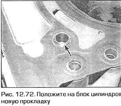
72. Place the new gasket on the block surface with the correct side facing up (fig. 12.72). Please note that if the head surface has been ground, a repair size gasket is produced for such cases, 0.3 mm thicker than the standard one.
73. Place the head on the block.
74. Lubricate the threads, heads and washers of the head bolts with engine oil. Insert the bolts into the holes. Note that bolts 7 through 10 (fig. 12.74) have an M8 thread and an E10 head, and bolts 1 through 6 have an M10 thread and an E12 head. Note that the bolt in position 10 is shorter than the others. Tighten the bolts in the specified sequence as specified in the Technical Data, i.e. tighten all bolts to the 1st stage torque, then tighten them to the required angle in the same sequence, etc. Bolts M8 and M10 are tightened to the same torque.
75. Screw the two mounting bolts into the chain tunnel and tighten them securely.
76. Screw and securely tighten the plug with a new sealing ring into the eccentric shaft motor bracket.
77. Align the left chain guide and insert the top pin into it. Tighten the pin securely and screw the plug into place with a new O-ring.
78. Turn the eccentric shaft by the hexagon on it so that the spring at its end is under the greatest tension.
79. Install the templates on the camshafts (see paragraph 3).
80. Return the crankshaft to the TDC position and insert the locking pin into the flywheel.
81. Install the camshaft phase adjuster solenoids, replacing them with new sealing rings. Install the solenoids brackets and securely tighten the screws securing them. Connect the electrical connectors.
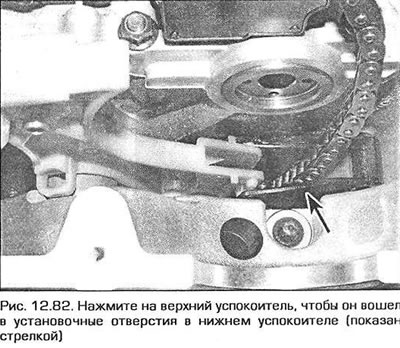
82. Lift the chain up and install the upper chain guide. Gently press the upper end of the left guide and press the upper guide so that it fits into the installation holes (fig. 12.82).
83. Screw in the upper bolt of the upper damper and tighten it only by hand for now.
84. Screw in the lower bolt of the upper damper and finally tighten both bolts - the lower and upper - to the required torque.
85. Finally install the sprockets, chain and camshaft phase adjusters as specified in paragraph 7.
86. Otherwise, installation is carried out in the reverse order of removal.
[The original version is on the portal «BMWMAN.ru»]
This article is available at russian, bulgarian, belarusian, ukrainian, serbian, croatian, romanian, polish, slovak, hungarian
Article verified: Ilyinsky Matvey
Share information:
Previous articles
БМВ E46: 4 cylinder engines
Next articles
Camshafts, rocker arms and hydraulic supports — removal and…
Valve timing drive (engine N42) — description and replacement of parts
Camshaft timing chain housing (M43TU engine) — removal and…
Timing Chain Sprockets and Tensioner — Removal and Installation
Timing chain — removal, inspection and installation
Valve timing drive (engine N42) — description and replacement of parts
Camshaft timing chain housing (M43TU engine) — removal and…
Timing Chain Sprockets and Tensioner — Removal and Installation
Timing chain — removal, inspection and installation
Similar articles on other types of BMW cars:
Removal and installation of cylinder head — engines M20, M21, M30 BMW 5 Series E34 (1988-1996)
Removal and installation the cylinder head / replacing the cylinder… BMW 5 Series E39 (1995-2003)
Cylinder head of gasoline engines of the M52 series — removal and… BMW 7 Series E32 (1986-1994)
Removal and installation cylinder head covers BMW 7 Series E38 (1994-2001)
Removal and installation the cylinder head BMW X3 E83 (2003-2010)
Removal and installation the lock cylinder BMW X5 E53 (1999-2006)
Link in different formats to this page
Visitor comments
No comments yet
- General information
- Manual
- Maintenance
- Power unit
- Engine repair
- Cooling system
- Power system (gasoline)
- Injection system (gasoline)
- Fuel system (diesel)
- Exhaust system
- Ignition system
- Charge and launch systems
- Transmission
- Car gearbox
- Clutch and drive shafts
- Chassis
- Brake system
- Suspension front and rear
- Steering
- Body
- Body care and repair
- Exterior
- Interior
- Electrical equipment
- Troubleshooting
- Lighting and signaling
- Equipment and devices
- Heater and air conditioner
- Electrical circuits
- General information
- Manual
- Repair on the road
- Weekly checks
- Maintenance
- Troubleshooting
- Power unit
- 4 cylinder engines
- 6 cylinder engines
- Engine overhaul
- Cooling and heating
- Fuel and exhaust system
- Starting and charging system
- Ignition system
- Transmission
- Clutch
- Mechanical gearbox
- Automatic gearbox
- Cardan and drive shafts
- Chassis
- Brake system
- Wheel suspension
- Steering
- Body
- Exterior
- Interior
- Electrical equipment
- Equipment and devices
- Electrical circuits
- General information
- Maintenance
- Power unit
- Engine repair
- Cooling system
- Ignition system
- Supply system
- Fuel injection system
- Exhaust system
- Transmission
- Clutch
- Car gearbox
- Front and rear axle
- Chassis
- Steering
- Brake system
- Body
- Exterior
- Interior
- Electrical equipment
- Heating system
- Equipment and devices
- Power devices
- Electrical circuits
- Power unit
- M10/M20 engine
- M40 engine
- Ignition system
- Lubrication system
- Cooling system
- Supply system
- Fuel injection
- Exhaust system
- Transmission
- Clutch
- Manual gearbox
- Front axle
- Rear axle
- Chassis
- Steering
- Brake system
- Body
- Exterior
- Interior
- Electrical equipment
- Heating system
- Equipment and devices
- Electrical circuits
- General information
- Specifications
- Operation and maintenance
- 4-cylinder engine
- Engine repair
- Cooling and lubrication system
- Supply system
- Ignition system
- 6-cylinder engine
- Engine repair
- Cooling and lubrication system
- Supply system
- Fuel injection system
- Ignition system
- Transmission
- Clutch
- 4-speed manual gearbox
- 5-speed manual gearbox
- Automatic gearbox
- Cardan and rear axle
- Chassis
- Steering
- Front suspension
- Rear suspension
- Brake system
- Electrical equipment
- Equipment and devices
- Electrical circuits