
- Home
- BMW 3 Series
- E46
- Power unit
- Ignition system
- Ignition coils — removal and installation
Ignition coils — removal and installation (BMW 3 Series E46)
4-cylinder engine M43TU
Removal
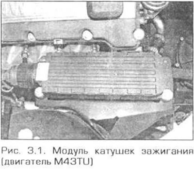
1. Each spark plug is equipped with a separate ignition coil. All coils are connected into a common module, which is located above the upper support of the right front suspension (Fig. 3.1).
2. Turn off the ignition.
3. Disconnect the electrical connector from the ignition coil module.
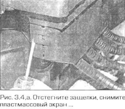
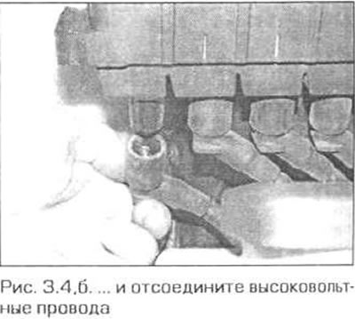
4. Unfasten the latches and remove the plastic screen from the ignition coil module. Disconnect the high-voltage wires from the module (fig. 3.4,a,b). Mark the wires to avoid confusion during installation. The cylinder numbers for connecting the corresponding wires are marked on the top of the module coils.
5. Loosen the coil module mounting bolts and remove the module from the body.
Installation
6. Installation is performed in reverse order. Do not mix up the high-voltage wires when connecting them to the module.
4-cylinder engine N42
Removal
7. Remove the two bolts securing the cover above the engine, lift the front edge of the cover and pull it forward.
8. At the rear of the engine compartment, turn the two fasteners 90° counterclockwise and remove the cabin filter cover. Pull the filter out of the housing.
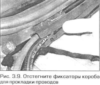
9. Unfasten the four fasteners of the box for laying the wires and remove the sleeves with wires from the box (Fig. 3.9).
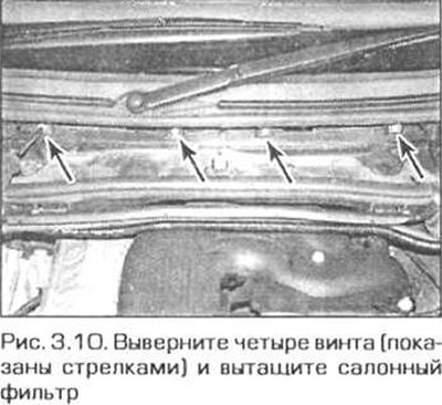
10. Unscrew the four screws and pull the cabin filter housing forward (Fig. 3.10).
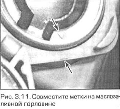
11. Unscrew the oil filler cap. Align the marks on the opening neck and on the neck (Fig. 3.11). Squeeze the unmarked sides of the neck and pull it out of the neck.
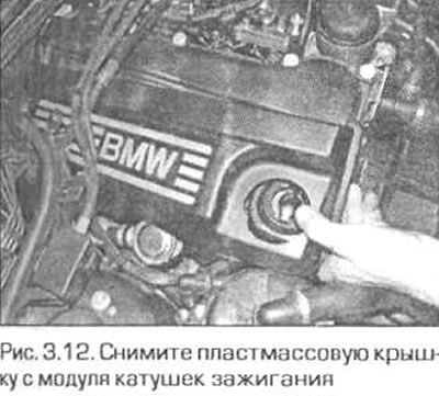
12. Remove the plastic cover from the ignition coil module (Fig. 3.12).
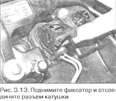
13. Open the coil electrical connector latches and disconnect the coil connector plugs (Fig. 3.13). Remove the coils from the spark plugs.
Installation
14. Installation is performed in the reverse order of removal. The protrusion on the cylinder head must enter the rubber seal on the underside of the coil.
6-cylinder engines
Removal
15. Each spark plug has its own coil. The coils are located directly above the spark plugs in the cylinder head cover.
16. Turn off the ignition.
17. Unscrew the oil filler cap.
18. Remove the air duct for the ventilation and heating system from the rear of the engine compartment as follows.
- a) Remove the cabin filter cover by turning its latches 90° counterclockwise. Pull the filter out of the housing.
- b) Unfasten the four fasteners of the box for laying the wires and remove the sleeves with wires from the box (Fig. 3.9).
- c) Remove the four screws and pull the cabin filter housing forward.
- d) In the left rear corner of the engine compartment, pull off the seal, turn the two fasteners counterclockwise and move the trim panel forward a little
- d) Remove the two screws and remove the air duct.
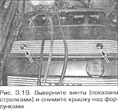
19. Remove the plugs from the plastic cover above the injectors, unscrew the screws and remove the cover (Fig. 3.19).
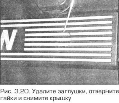
20. Remove the plastic cover from the cylinder head cover. To remove the outer cover, remove the plugs, unscrew the two nuts, lift the cover and slide it forward (Fig. 3.20).
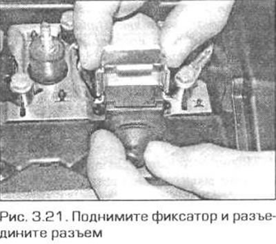
21. Lift the coil connector lock and disconnect the connector plug from the coil (Fig. 3.21). If all coils need to be removed, disconnect the connectors of all coils and disconnect the ground busbar on the front side of the timing chain cover. The wiring harness can now be released from the fasteners and moved to the side.
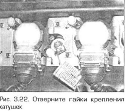
22. Remove the two coil mounting nuts. Note the ground wires and brackets that are secured with the same nuts. If the bracket is secured with nuts from two different coils, you may need to remove the nut from the adjacent coil and remove the bracket so that it does not interfere with the removal of the desired coil (Fig. 3.22). Keep in mind that the coils are spring-loaded and will rise as the nuts are removed.
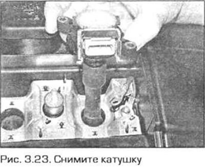
23. Remove the coil from the spark plug and from the cylinder head cover (Fig. 3.23).
Installation
24. Installation is performed in reverse order. Do not forget to secure all the brackets and ground wires that were before disassembly with the coil nuts
(Examine the original source using the link on the website BMWMAN.RU)
This article is available at russian, bulgarian, belarusian, ukrainian, serbian, croatian, romanian, polish, slovak, hungarian
Article verified: Ilyinsky Matvey
Share information:
Previous articles
БМВ E46: Ignition system
Next articles
Similar articles on other types of BMW cars:
Removal and installation / checking of ignition coils BMW 5 Series E39 (1995-2003)
Features of removal and installation of the ignition distributor… BMW 5 Series E12 (1972-1981)
Ignition coils — removal, inspection and installation BMW 7 Series E32 (1986-1994)
Removal and installation the ignition switch and steering wheel lock BMW 7 Series E38 (1994-2001)
Pistons — removal and installation BMW X3 E83 (2003-2010)
Removal and installation the ignition coil BMW X5 E53 (1999-2006)
Link in different formats to this page
Visitor comments
No comments yet
- General information
- Manual
- Maintenance
- Power unit
- Engine repair
- Cooling system
- Power system (gasoline)
- Injection system (gasoline)
- Fuel system (diesel)
- Exhaust system
- Ignition system
- Charge and launch systems
- Transmission
- Car gearbox
- Clutch and drive shafts
- Chassis
- Brake system
- Suspension front and rear
- Steering
- Body
- Body care and repair
- Exterior
- Interior
- Electrical equipment
- Troubleshooting
- Lighting and signaling
- Equipment and devices
- Heater and air conditioner
- Electrical circuits
- General information
- Manual
- Repair on the road
- Weekly checks
- Maintenance
- Troubleshooting
- Power unit
- 4 cylinder engines
- 6 cylinder engines
- Engine overhaul
- Cooling and heating
- Fuel and exhaust system
- Starting and charging system
- Ignition system
- Transmission
- Clutch
- Mechanical gearbox
- Automatic gearbox
- Cardan and drive shafts
- Chassis
- Brake system
- Wheel suspension
- Steering
- Body
- Exterior
- Interior
- Electrical equipment
- Equipment and devices
- Electrical circuits
- General information
- Maintenance
- Power unit
- Engine repair
- Cooling system
- Ignition system
- Supply system
- Fuel injection system
- Exhaust system
- Transmission
- Clutch
- Car gearbox
- Front and rear axle
- Chassis
- Steering
- Brake system
- Body
- Exterior
- Interior
- Electrical equipment
- Heating system
- Equipment and devices
- Power devices
- Electrical circuits
- Power unit
- M10/M20 engine
- M40 engine
- Ignition system
- Lubrication system
- Cooling system
- Supply system
- Fuel injection
- Exhaust system
- Transmission
- Clutch
- Manual gearbox
- Front axle
- Rear axle
- Chassis
- Steering
- Brake system
- Body
- Exterior
- Interior
- Electrical equipment
- Heating system
- Equipment and devices
- Electrical circuits
- General information
- Specifications
- Operation and maintenance
- 4-cylinder engine
- Engine repair
- Cooling and lubrication system
- Supply system
- Ignition system
- 6-cylinder engine
- Engine repair
- Cooling and lubrication system
- Supply system
- Fuel injection system
- Ignition system
- Transmission
- Clutch
- 4-speed manual gearbox
- 5-speed manual gearbox
- Automatic gearbox
- Cardan and rear axle
- Chassis
- Steering
- Front suspension
- Rear suspension
- Brake system
- Electrical equipment
- Equipment and devices
- Electrical circuits