
4-cylinder M43TU engine
Withdrawal
1. Two knock sensors are bolted to the left wall of the cylinder block. One sensor registers detonation in cylinders No. 1 and 2, and the second - in cylinders 3 and 4.
2. Relieve pressure in the fuel system (see chapter 4A) and disconnect the negative battery cable.
3. Remove the top section of the intake manifold (see chapter 4A).
4. Disconnect electric sockets of gauges of position of camshaft and cranked shaft.
5. Turn out two bolts of fastening of a box with wires to the bottom section of an inlet collector.
6. Disconnect the plug of the electrical connector from the knock sensor and release the connector from the bracket.
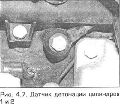
7. The knock sensor for cylinders No. 1 and 2 located between the oil filter and the intake manifold can be removed as follows (pic. 4.7).
- A) The sensor can be reached from above through the opening between the intake manifold pipes of cylinders 2 and 3, if the fuel line is first disconnected from the fuel rail. Prepare for fuel to flow from the connection. Plug both holes to keep dirt out of the fuel system.
- b) To provide enough space to remove the sensor, you must first unscrew the bolt securing the cooling system pipe and slightly pull the pipe away from the engine.
- V) Turn out a bolt of fastening of the gauge and remove the gauge from the engine.
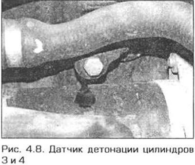
8. Access to the second sensor is obvious. Just unscrew the sensor mounting bolt and remove it from the engine (pic. 4.8).
Installation
9. Before installing the sensor, thoroughly clean the mating surfaces of the cylinder block and the sensor itself.
10. Install the sensor in place and tighten its bolt to the required torque.
11. The rest of the installation is carried out in the reverse order of removal, taking into account the following remarks.
- A) Connect all electrical connectors.
- b) Install the upper section of the intake manifold as instructed in chapter 4A.
- V) Fill the fuel system as directed in Section 4A.
4-cylinder N42 engine
Withdrawal
12. Disconnect the negative battery cable.
13. Remove the intake manifold as directed in chapter 4A.
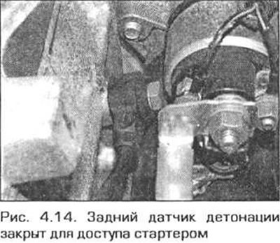
14. Two knock sensors are installed on the engine. The rear sensor is closed to access by the starter. If you want to remove the rear sensor, you must first remove the starter (pic. 4.14).
15. Trace the wiring of the sensors and disconnect their electrical connectors.
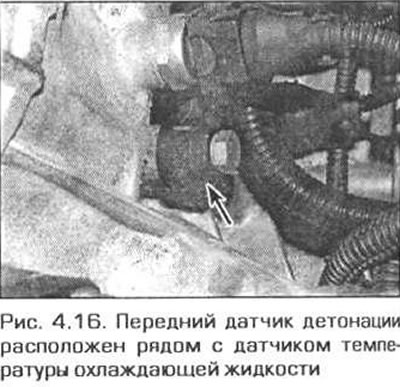
16. Turn out bolts and remove gauges (pic. 4.16).
Installation
17. Install the sensor in sequence. reverse withdrawal. Before installation carefully clear interfaced surfaces of the gauge and the block of cylinders. Tighten the sensor mounting bolt to the required torque.
6-cylinder engines
Withdrawal
18. These engines have two knock sensors on the left wall of the cylinder block. One sensor monitors knock on cylinders 1 to 3, the other controls knock on cylinders 4 to 6.
19. Disconnect the negative battery cable.
20. Remove the intake manifold (see chapter 4A).
21. Locate the sensor connector bracket located under the idle air valve.
Attention! If both sensors need to be removed, label the connectors. to properly connect them during installation. Incorrect connection of the connectors can result in serious engine damage.
22. Release the connector from the retainer and disconnect it (their).
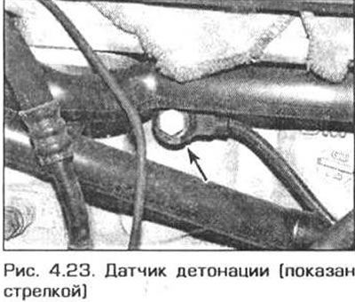
23. Turn out a bolt of fastening of the gauge and remove the gauge from the engine. The knock sensor for cylinders 1-3 is located below the temperature sensors in the cylinder head (pic. 4.23). The sensor for cylinders 4-6 is located behind the connector bracket.
Installation
24. Before installing the sensor, thoroughly clean the mating surfaces of the cylinder block and the sensor itself.
25. Install the sensor in place and tighten its bolt to the required torque.
26. Connect the connectors of the sensors and fix them on the bracket. Do not mix up connectors.
Attention! Incorrect connection of the connectors can result in serious engine damage.
27. Reinstall the intake manifold (see chapter 4A).