
Note. When installing the cover, a new gasket may be required (see text).
M43TU engine
Withdrawal
1. At the rear of the engine compartment, remove the pollen filter cover by turning its locks 90°counterclockwise. Remove filter (if necessary, see chapter 1).
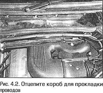
2. Unfasten the four latches of the cable management box and remove the wire sleeves from the cable box (pic. 4.2).
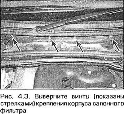
3. Remove the four screws and pull the cabin filter housing forward, (pic. 4.3).
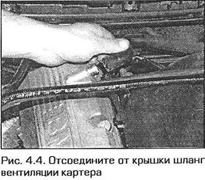
4. Disconnect the crankcase ventilation hose from the cylinder head cover (pic. 4.4). Turn out bolts of fastening of a cover and remove it from a head of cylinders. Remove the gasket.
Installation
5. Thoroughly wipe the mating surfaces of the cylinder head and cover.
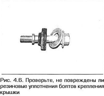
6. Check up a condition of rubber consolidations of bolts of fastening of a cover. If necessary, replace them. Put the seals and washers on the bolts (pic. 4.6).
7. Inspect the cover gasket and replace if necessary. Insert the gasket into the cover.
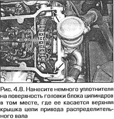
8. Apply a small amount of sealant to the surface of the cylinder head where the upper camshaft timing chain cover touches it (pic. 4.8).
9. Install the cover on the cylinder head, aligning the tab on the gasket with the notch on the back of the cylinder head.
10. Install the cover bolts and tighten them securely.
N42 engine
Withdrawal
11. Turn away two nuts of fastening of the top plastic cover of the engine. Lift the front edge of the cover and pull it forward.
12. At the rear of the engine compartment, remove the cabin filter cover by turning its locks 90°counterclockwise. Remove the cover and take out the filter.
13. Unfasten the four latches of the wiring box and remove the sleeves with wires from the box (see fig. 4.2).
14. Remove the four screws and pull the cabin filter housing forward (see fig. 4.3).
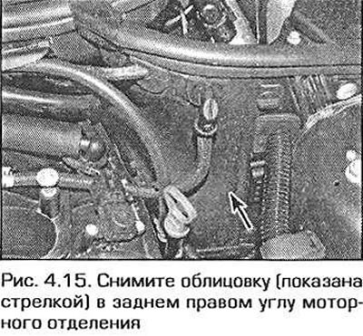
15. In the rear left corner of the engine compartment, lift up the sealing harness, release the lining from the clamps and slightly pull it forward (pic. 4.15).
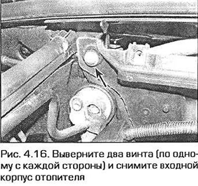
16. Remove the two slotted screws securing the heater inlet housing and remove the housing (pic. 4.16).
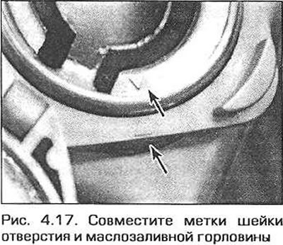
17. Remove the oil fill plug. Align the marks on the neck of the hole and the neck (pic. 4.17). Squeeze the neck of the neck in a direction perpendicular to the marks and pull the neck out of the neck.
18. Pull out the plastic cover of the ignition coils from the rubber bushings.
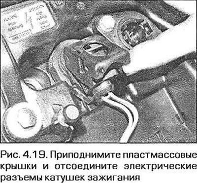
19. Hook the right edge of the ignition coil covers (over the candles) and disconnect the coil connectors (pic. 4.19). After that, pull the coils from the candles.
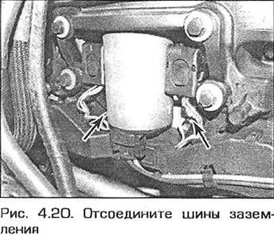
20. Disconnect the electrical connectors for the camshaft timing motor and eccentric position sensor, then release the ignition coil harness from the mounts on the cylinder head cover and move the harness to the side. Note the two ground terminals on the cylinder head cover (pic. 4.20).
21. Squeeze the connection of the crankcase ventilation hose to the cylinder head cover and pull the hose off the cover.
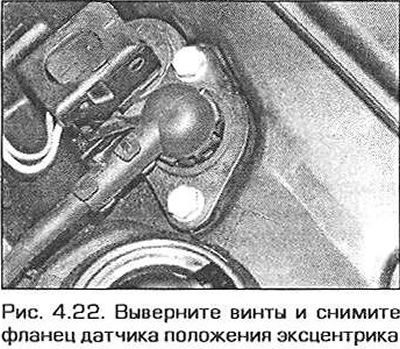
22. Remove the two screws and remove the eccentric position sensor flange (pic. 4.22).
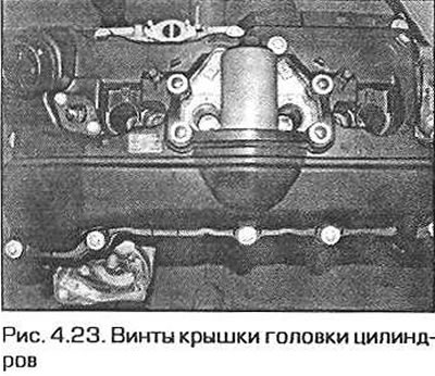
23. Turn out screws of fastening of a cover of a head of cylinders and remove a cover (pic. 4.23). Please note that the screws are of different lengths - do not confuse them when assembling. If the cover gasket is in good condition, it can be reused. If not, replace it.
Note. At the time of writing, the gasket could only be purchased with a cover and screws. For more up-to-date information, contact your BMW dealer.
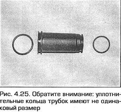
24. If necessary, take out from a head of cylinders sealing tubes of candles.
Installation
25. Install the spark plug tube o-rings. Moisten them with engine oil and push them into the holes in the cylinder head (pic. 4.25).
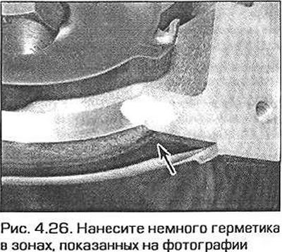
26. Apply a thin coat of Drei Bond Sealant (can be purchased from a dealer) in the zones shown in Fig. 4.26 on the front and rear sides of the cylinder head.
27. Put on a cover of a head of cylinders a lining and establish a cover into place. Screw in the cover fixing screws and tighten them hand-tight for the time being.
28. Moisten the sealing ring of the flange of the eccentric position sensor, insert the flange, screw in the screws and tighten them until hand-tight.
29. Make sure that the gasket under the cover has not moved, and tighten the screws securing it to the required torque in a diagonal sequence.
30. Tighten the eccentric position sensor flange bolts securely.
31. The rest of the assembly is performed in the reverse order of disassembly.