
Table of contents: Engine M43TU ↓ Engine N42 ↓
- Home
- BMW 3 Series
- E46
- Power unit
- 4 cylinder engines
- Timing chain — removal, inspection and installation
Timing chain — removal, inspection and installation (BMW 3 Series E46)
Engine M43TU
Removal
1. Turn the crankshaft to the BMT position (see paragraph 3) and fix the flywheel.
2. Remove both chain covers as described in paragraph 6.
3. Remove the camshaft sprocket mounting bolts and remove the camshaft position sensor rotor. Remember how the rotor was installed.
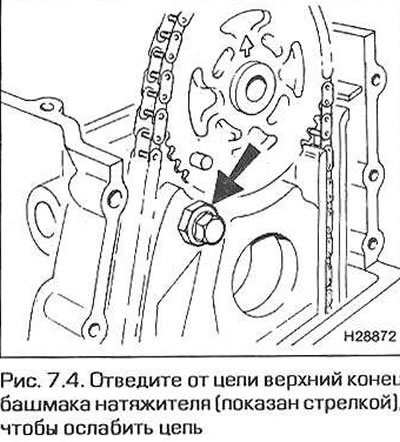
4. Move the upper end of the tensioner shoe away from the chain to loosen the chain and remove the sprocket from the camshaft (Fig. 7.4). Remove the sprocket, then disconnect the chain from the sprocket.
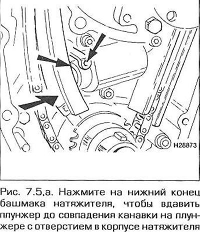
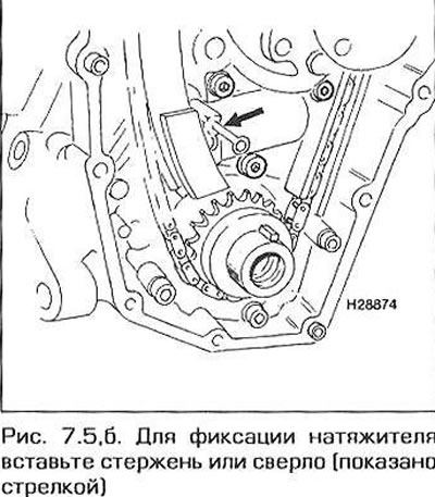
5. Press the lower end of the tensioner shoe to push in the tensioner plunger. Push the plunger until its groove is against the hole in the tensioner body. Lock the plunger in this position by inserting a metal rod or a drill of the appropriate size into the hole and into the groove of the plunger (fig. 7.5,a,b).
6. Remember how the chain is routed relative to the chain guide and tensioner shoe.
7. Having fixed the tensioner plunger, remove the chain together with the crankshaft sprocket.
8. If necessary, you can also remove the tensioner shoe and chain guide.
Inspection
9. The chain should be replaced if the sprocket teeth or the chain itself are worn. Chain wear is noticeable by significant play in its links and by noise when the engine is running. On a worn chain, the rollers of the links may have noticeable grooves. If there is even the slightest suspicion of chain failure, replace it. It is recommended to replace the chain in any case if the engine is removed and disassembled for major repairs.
10. Inspect the sprocket teeth for wear. A normal tooth is V-shaped. When worn, the working side of the tooth is worn down, so that the worn tooth takes on the shape of a hook. Wear is especially noticeable when comparing the working side of the tooth with the non-working side. Worn sprockets should be replaced. Also inspect the working surfaces of the damper and the tensioner shoe. Worn parts should also be replaced.
Installation
11. Make sure that the engine is in the installation position (TDC of piston No.1) and that the engine flywheel is locked. Check the position of the camshaft using a template (see paragraph 3).
12. Reinstall the tensioner shoe and chain guide (if any were removed).
13. Insert the woodruff key into the crankshaft nose groove (or make sure it is already there).
14. Place the chain on the crankshaft sprocket, then install the sprocket and chain onto the crankshaft. Route the chain in the guide and around the tensioner shoe.
15. Remove the locking rod from the tensioner and allow the tensioner to tension the chain.
16. Press the top end of the tensioner shoe to loosen the chain and allow the sprocket to be inserted onto the camshaft. Insert the sprocket so that the pointer arrow points straight up.
17. Place the sprocket on the camshaft, aligning the bolt holes in the shaft flange with the center of the oblong holes in the sprocket (the camshaft must be in the installation position and secured against rotation with a template - see paragraph 3). Screw in the sprocket mounting bolts and tighten them as much as possible by hand.
18. Release the upper end of the tensioner shoe, then tighten the camshaft sprocket mounting bolts to the specified torque.
19. Remove the crankshaft lock and camshaft template.
20. Install the chain covers as described in paragraph 6.
Engine N42
Removal
21. Turn the crankshaft to the TDC position (see paragraph 3) and fix the flywheel.
22. Remove the eccentric motor as described in paragraph 10.
23. Remove the pulley with the damper and the hub from the crankshaft (see paragraph 5). Note: After loosening the hub bolt, the chain sprocket, oil pump and balance shafts will no longer be clamped on the shaft and will be able to rotate independently of it. Therefore, when loosening the hub bolt, lock the crankshaft and camshaft in the installation position as indicated in paragraph 3.
24. Raise the front of the vehicle and support it with secure supports.
25. Attach a sling to the front engine lifting eye and use a lifting device to pull the engine up to remove its weight from the mounts.
26. Remove the front subframe as described in paragraph 15. To do this, it is not necessary to disconnect the steering gear from the subframe - simply unscrew the connecting bolt of the flexible joint of the steering column and disconnect the steering gear pinion from the column.
27. Remove the pan as described in paragraph 13.
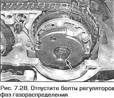
28. Secure the camshafts as described in paragraph 3, then loosen the valve timing adjustment device bolts at the ends of the camshafts (Fig. 7.28).
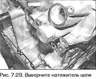
29. On the front right side of the cylinder block, unscrew the chain tensioner (Fig. 7.29). Be prepared for oil to flow from the tensioner. When installing the tensioner, the sealing washer under the plug must be replaced with a new one.
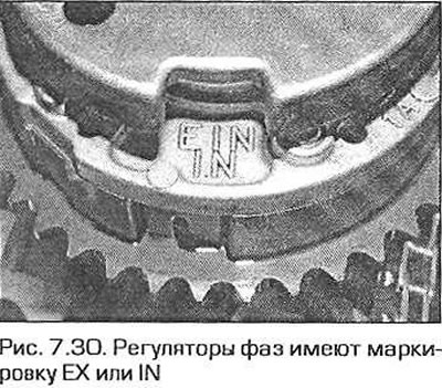
30. Completely unscrew the exhaust shaft phase adjuster bolt and remove the adjuster from the shaft together with the shaft position sensor rotor and sprocket. Do the same on the intake shaft. Keep in mind that the adjusters are marked IN (intake) and EX (outlet). Do not mix them up when installing (Fig. 7.30).
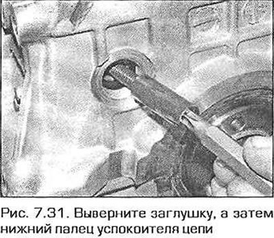
31. Unscrew the plug on the right side above the front crankshaft seal and unscrew the lower pin of the chain guide (Fig. 7.31).
32. Disconnect the electrical connector of the intake camshaft position sensor by squeezing the tabs of the connector plug.
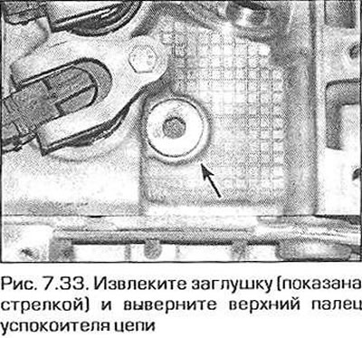
33. Remove the plug behind the intake camshaft position sensor and unscrew the upper pin of the chain guide (Fig. 7.33).
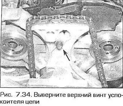
34. Unscrew the upper chain guide screw from the cylinder head (Fig. 7.34).
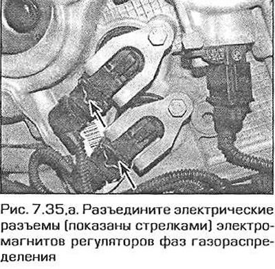
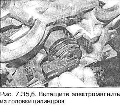
35. On the front side of the cylinder head, disconnect the electrical connectors of the solenoids of the valve timing adjusters of the intake and exhaust camshafts (fig. 7.35,a). Remove the screws and pull out the electromagnets (fig. 7.35.6). Discard the sealing rings - new ones will be required for installation.
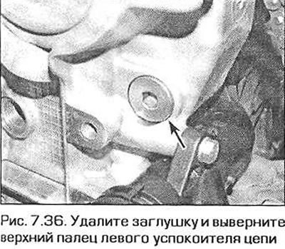
36. Remove the plug from the left side of the chain cover and unscrew the upper pin of the left chain guide (Fig. 7.36).
37. Remove the chain together with the dampers and the crankshaft sprocket.
38. Pull the chain down from the guides and disconnect it from the crankshaft sprocket.
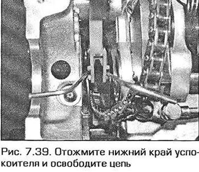
39. Press down the lower edge of the chain guide and completely release the chain (Fig. 7.39).
Inspection
40. The chain should be replaced if the teeth of the sprockets or the chain itself are worn. Chain wear is noticeable by significant play in its links and by noise when the engine is running. On a worn chain, the rollers of the links may have noticeable grooves. If there is even the slightest suspicion of a chain malfunction, replace it. It is recommended to replace the chain in any case if the engine is removed and disassembled for major repairs.
41. Inspect the sprocket teeth for wear. A normal tooth is V-shaped. When worn, the working side of the tooth is worn down, so that the worn tooth takes on the shape of a hook. Wear is especially noticeable when comparing the working side of the tooth with the non-working side. Worn sprockets should be replaced. Also inspect the working surfaces of the damper and the tensioner shoe. Worn parts should also be replaced.
Installation
42. Press the lower edge of the guide and pull the chain through (see fig. 7.39).
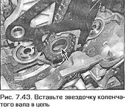
43. Insert the crankshaft sprocket into the lower loop of the chain. The sprocket flange should be directed towards the crankshaft (Fig. 7.43).
44. Pull the chain up through the guide until the bottom edge of the guide grips the sprocket. Hold the chain and sprocket in this position.
45. Lower this entire assembly into the chain housing and install the sprocket onto the end of the crankshaft.
46. Insert the lower chain guide pin through the hole in the chain cover, screw it in and tighten it securely. Screw in the plug with a new sealing ring and tighten it to the specified torque.
47. Insert the upper chain guide pin through the hole in the chain cover, screw it in and tighten it securely. Screw in the plug with a new sealing ring and tighten it to the specified torque.
48. Install the pulley hub onto the crankshaft nose and secure it with a bolt, but only by hand for now.
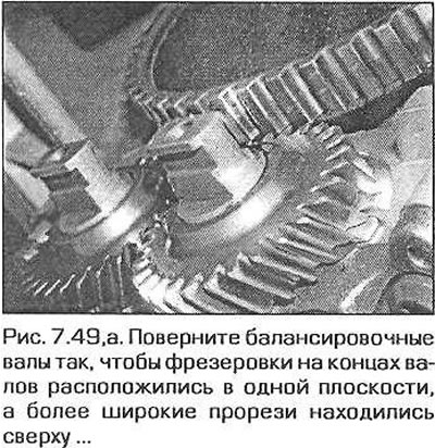
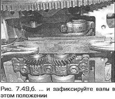
49. Working underneath the vehicle, rotate the balance shafts so that the millings on the ends of the shafts are in the same plane and the wider slots are on top (fig. 7.49,a). Using two metal strips and a clamp, secure the shafts in this position (fig.7.49,b).
50. Check that the crankshaft is still in the installation position and the flywheel is secured with a suitable tool. If so, tighten the pulley hub bolt to 60 Nm (higher torque may damage the locking device or the engine crankcase).
51. Remove all locking devices from the balance shafts.
52. Install the solenoids of the valve timing adjustment units of both camshafts. When installing the solenoids, replace the sealing rings with new ones. Securely tighten the mounting screws and connect the electrical connectors.
53. Install both upper chain guide mounting screws and tighten them securely. Install the lower screw cap with the sealing ring and tighten the cap to the specified torque.
54. Connect the intake camshaft position sensor connector.
55. Raise the chain and hold it taut. Insert the intake camshaft phase adjuster into the chain and place it and the sensor rotor on the end of the shaft. Secure the assembly with a new bolt. Tighten the bolt just enough to eliminate any play, but no more. Repeat the same steps on the exhaust shaft. Note that although the phase adjusters are marked IN and EX, the sensor rotors are the same.
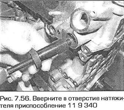
56. Make sure that the chain lies correctly on the surface of the tensioner shoe. Screw the original device 11 9 340 (Fig. 7.56) into the hole of the tensioner and turn the adjusting screw of the device until it touches the shoe, without tensioning the chain.
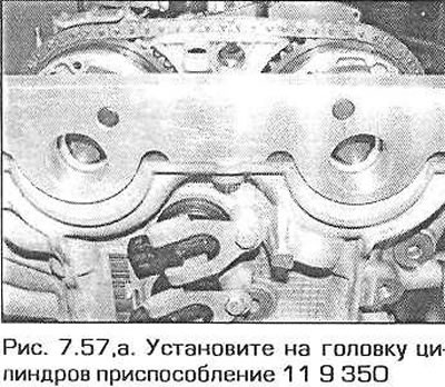
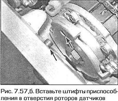
57. Install tool 119350 on the cylinder head (fig. 7.57,a). Insert the pins of the tool into the holes of the camshaft position sensor rotors (fig. 7.57.6). Screw the fixture to the cylinder head using two M6 bolts included in the fixture kit.
58. Loosen the bolts securing the phase regulators and rotors to the shafts by half a turn, then tighten them so that their heads just touch the rotors, eliminating any play.
59. Tighten the chain slightly by tightening the adjusting screw of the device to a torque of approximately 0.6 Nm. If you do not have a torque wrench that can control such a small torque, simply tighten the adjusting screw of the device by hand enough to eliminate the chain play.
60. Tighten the bolts of both phase regulators to the required torque.
61. Remove the screws and remove tool 11 9 350 from the cylinder head.
62. Loosen the adjusting screw of tool 11 9 340 and unscrew the tool from the tensioner hole.
63. Remove any remaining oil from the tensioner plunger, replace the plug sealing ring, insert the tensioner parts into the corresponding hole and tighten the plug to the required torque.
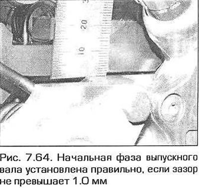
64. Remove the crankshaft and camshaft locking pins and rotate the crankshaft two full revolutions. Make sure that the crankshaft and camshaft locking pins can be reinserted. A clearance of 1.0 mm between the exhaust shaft (1.0 mm) and intake shaft (0.5 mm) fixtures and the upper surface of the cylinder head under the gasket on the exhaust manifold side is allowed (Fig. 7.64).
65. After checking the clearances, remove the installation tools, tighten the crankshaft hub mounting bolt to the required torque, holding the shaft from turning using the method previously used when loosening the bolt.
66. The rest of the assembly is carried out in the reverse order of disassembly.
The original version is on the portal: bmwman.ru
This article is available at russian, bulgarian, belarusian, ukrainian, serbian, croatian, romanian, polish, slovak, hungarian
Article verified: Ilyinsky Matvey
Share information:
Previous articles
БМВ E46: 4 cylinder engines
Next articles
Timing Chain Covers — Removal and Installation
Crankshaft pulley and vibration damper — removal and installation
Cylinder Head Cover — Removal and Installation
Setting the engine to the top dead center position of piston No. 1
Compression Test — Description and Analysis of Results
Crankshaft pulley and vibration damper — removal and installation
Cylinder Head Cover — Removal and Installation
Setting the engine to the top dead center position of piston No. 1
Compression Test — Description and Analysis of Results
Timing Chain Sprockets and Tensioner — Removal and Installation
Camshaft timing chain housing (M43TU engine) — removal and…
Valve timing drive (engine N42) — description and replacement of parts
Camshafts, rocker arms and hydraulic supports — removal and…
Cylinder head — removal, inspection and installation
Camshaft timing chain housing (M43TU engine) — removal and…
Valve timing drive (engine N42) — description and replacement of parts
Camshafts, rocker arms and hydraulic supports — removal and…
Cylinder head — removal, inspection and installation
Similar articles on other types of BMW cars:
Removal, inspection and installation of the timing chain and its… BMW 5 Series E28 (1981-1988)
Removal and installation, inspection of the rear shock absorber BMW 5 Series E34 (1988-1996)
Timing Chain Covers — Removal and Installation BMW 7 Series E32 (1986-1994)
Removal and installation timing chain covers BMW 7 Series E38 (1994-2001)
Pistons — removal and installation BMW X3 E83 (2003-2010)
Removal and installation the engine BMW X5 E53 (1999-2006)
Link in different formats to this page
Visitor comments
No comments yet
- General information
- Manual
- Maintenance
- Power unit
- Engine repair
- Cooling system
- Power system (gasoline)
- Injection system (gasoline)
- Fuel system (diesel)
- Exhaust system
- Ignition system
- Charge and launch systems
- Transmission
- Car gearbox
- Clutch and drive shafts
- Chassis
- Brake system
- Suspension front and rear
- Steering
- Body
- Body care and repair
- Exterior
- Interior
- Electrical equipment
- Troubleshooting
- Lighting and signaling
- Equipment and devices
- Heater and air conditioner
- Electrical circuits
- General information
- Manual
- Repair on the road
- Weekly checks
- Maintenance
- Troubleshooting
- Power unit
- 4 cylinder engines
- 6 cylinder engines
- Engine overhaul
- Cooling and heating
- Fuel and exhaust system
- Starting and charging system
- Ignition system
- Transmission
- Clutch
- Mechanical gearbox
- Automatic gearbox
- Cardan and drive shafts
- Chassis
- Brake system
- Wheel suspension
- Steering
- Body
- Exterior
- Interior
- Electrical equipment
- Equipment and devices
- Electrical circuits
- General information
- Maintenance
- Power unit
- Engine repair
- Cooling system
- Ignition system
- Supply system
- Fuel injection system
- Exhaust system
- Transmission
- Clutch
- Car gearbox
- Front and rear axle
- Chassis
- Steering
- Brake system
- Body
- Exterior
- Interior
- Electrical equipment
- Heating system
- Equipment and devices
- Power devices
- Electrical circuits
- Power unit
- M10/M20 engine
- M40 engine
- Ignition system
- Lubrication system
- Cooling system
- Supply system
- Fuel injection
- Exhaust system
- Transmission
- Clutch
- Manual gearbox
- Front axle
- Rear axle
- Chassis
- Steering
- Brake system
- Body
- Exterior
- Interior
- Electrical equipment
- Heating system
- Equipment and devices
- Electrical circuits
- General information
- Specifications
- Operation and maintenance
- 4-cylinder engine
- Engine repair
- Cooling and lubrication system
- Supply system
- Ignition system
- 6-cylinder engine
- Engine repair
- Cooling and lubrication system
- Supply system
- Fuel injection system
- Ignition system
- Transmission
- Clutch
- 4-speed manual gearbox
- 5-speed manual gearbox
- Automatic gearbox
- Cardan and rear axle
- Chassis
- Steering
- Front suspension
- Rear suspension
- Brake system
- Electrical equipment
- Equipment and devices
- Electrical circuits