
Table of contents: Engine M43TU ↓ Engine N42 ↓
- Home
- BMW 3 Series
- E46
- Power unit
- 4 cylinder engines
- Setting the engine to the top dead center position of piston No. 1
Setting the engine to the top dead center position of piston No. 1 (BMW 3 Series E46)
Note: To fix the engine in the TDC position and to check the correct position of the camshafts, special devices are needed. Some of them can be made independently (see text).
1. Top dead center (TDC) is the top position of each piston as it moves up and down during engine operation. Each piston reaches TDC twice per working cycle - at the end of the compression stroke and at the end of the exhaust stroke. Usually, the engine position when the piston in cylinder #1 is at TDC of the compression stroke is considered to be the installation position. The cylinder numbering starts from the timing chain.
2. Setting the engine to the TDC position of piston No.1 requires many disassembly, assembly and repair procedures, such as removing and installing the timing chain, camshafts, etc.
3. The operation of setting the engine to TDC varies depending on the engine model.
Engine M43TU
4. Remove the cylinder head cover (see paragraph 4).
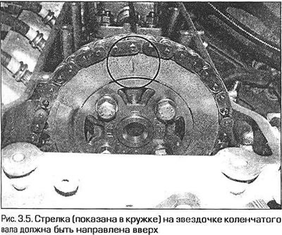
5. Turn the crankshaft clockwise so that the arrow on the crankshaft sprocket points straight up (Fig. 3.5). The crankshaft can be turned with a socket or open-end wrench by the head of its central bolt.
6. Remove the plug from the left side of the engine rear flange.
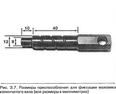
7. To fix the crankshaft in the installation position, a special device is required. You can use the branded device 11 2 300, but you can also make it yourself (Fig. 3.7).
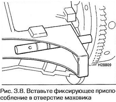
8. Insert the rod through the hole in the engine flange into the flywheel hole. If necessary, turn the crankshaft slightly left and right (Fig. 3.8).
9. Now the crankshaft is fixed in the TDC position of piston No.1.
10. When the engine shafts are installed correctly, the sides of the square flange on the front end of the camshaft should be perpendicular to the top plane of the cylinder head (this can be checked with a square), and the holes in the flange should be on top.
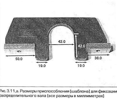
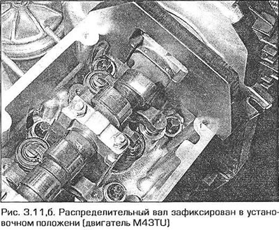
11. For some operations it is necessary to fix not only the crankshaft but also the camshaft at TDC. For this purpose, a device (template) can be made, the dimensions of which are shown in Fig. 3.11,a. When the camshaft is installed correctly, the device is put on top of the camshaft flange and holds the shaft from turning (fig. 3.11.6). Also keep in mind that at the moment when piston #1 is at TDC, piston #4 is completing the exhaust stroke. This means that both valves of cylinder #4 are slightly open - the exhaust valve is closing and the intake valve is opening. The cams of cylinder #4 are pushing on the rocker arms.
12. Do not attempt to turn the crankshaft if the flywheel or camshaft is secured with devices - this may damage the engine. If it is necessary to leave the engine in a secured position for a long time, leave appropriate warnings in the passenger compartment and in the engine compartment. This will reduce the likelihood of an attempt to start the engine with the starter.
Engine N42
13. Remove the cylinder block cover (paragraph 4).
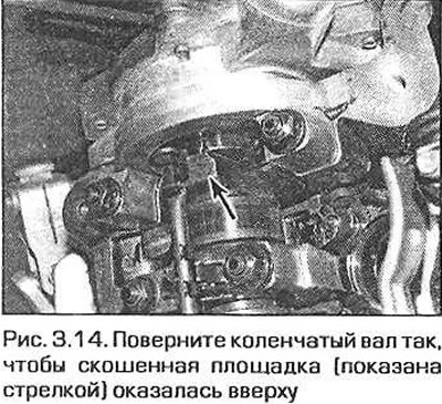
14. Turn the crankshaft clockwise so that the chamfered area on the crankshaft flange faces upward (Fig. 3.14). The crankshaft can be turned with a socket or open-end wrench by the head of its central bolt.
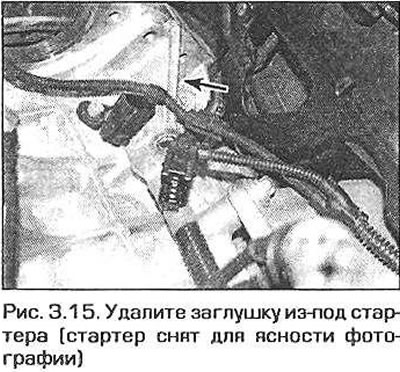
15. Remove the plug from the left side of the rear engine flange under the starter. Access to the flange is difficult. If necessary, remove the crankcase guard from under the engine. You can also remove the front amplifier (see paragraph 14). After this, you can get to the plug from below. Alternatively, remove the intake manifold (see chapter 4A) and free access to the flange from above (Fig. 3.15).
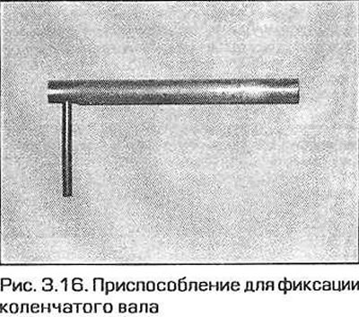
16. To fix the crankshaft in the installation position, a special device is required. You can use the branded device 119 190, but you can also make it yourself (Fig. 3.16) from a rod with a diameter of 8 mm and a length of about 80 mm. In order to be able to pull the device out of the flywheel, we drilled a hole in one end of it and screwed a second rod into it.
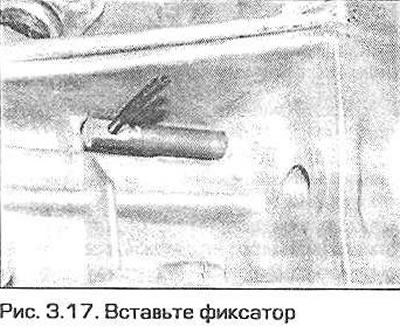
17. Insert the locking rod through the hole in the engine flange into the hole in the flywheel. If necessary, turn the crankshaft slightly left and right (Fig. 3.17). Note: In models with automatic transmission, there is a risk of making a mistake and inserting the rod into the large hole in the faceplate. Make sure that the crankshaft cannot be turned with the rod inserted.
18. Now the crankshaft is fixed in the TDC position of piston No.1.
19. Make sure that the camshafts are also in the installation position by trying to turn the camshafts towards each other. Use a square bar to turn the intake shaft and an open-end wrench to turn the exhaust shaft (there is a hex key on the shaft). If at least one shaft can be turned, continue turning it until it reaches the stop. If the camshafts cannot be turned, then the engine is locked in the installation position.
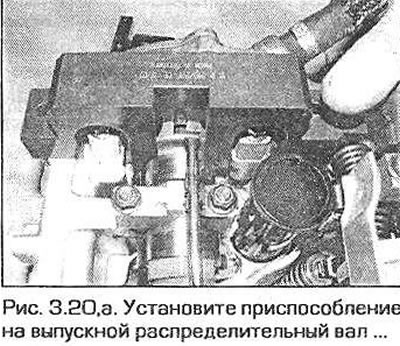
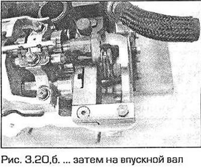
20. In this position, special branded tool 11 9 292 can be placed on the front end of the intake camshaft, and tool 11 9 291 on the end of the exhaust camshaft. If the shafts are correctly turned, the tools should be easily inserted and reach the corresponding areas on the upper side of the cylinder head cover. Secure the tool for fixing the exhaust camshaft with screws, and tighten the screws securing the tool for the intake camshaft (fig. 3.20, a, b). These devices fix the camshafts in such a way that the flat sides of their ends are installed perpendicular to the plane of the cylinder head.
21. Do not attempt to turn the crankshaft if the flywheel or camshaft is fixed with devices - this may damage the engine. If it is necessary to leave the engine fixed for a long time, leave appropriate warnings in the passenger compartment.
This article is available at russian, bulgarian, belarusian, ukrainian, serbian, croatian, romanian, polish, slovak, hungarian
Article verified: Ilyinsky Matvey
Share information:
Previous articles
БМВ E46: 4 cylinder engines
Next articles
Similar articles on other types of BMW cars:
Bringing the piston of the first cylinder to the top dead center… BMW 5 Series E28 (1981-1988)
Ignition key position BMW 5 Series E12 (1972-1981)
Setting the first cylinder to top dead center (TDC) BMW 7 Series E32 (1986-1994)
Starting the engine from an external power source BMW X3 E83 (2003-2010)
Correct seating position BMW X5 E53 (1999-2006)
Link in different formats to this page
Visitor comments
No comments yet
- General information
- Manual
- Maintenance
- Power unit
- Engine repair
- Cooling system
- Power system (gasoline)
- Injection system (gasoline)
- Fuel system (diesel)
- Exhaust system
- Ignition system
- Charge and launch systems
- Transmission
- Car gearbox
- Clutch and drive shafts
- Chassis
- Brake system
- Suspension front and rear
- Steering
- Body
- Body care and repair
- Exterior
- Interior
- Electrical equipment
- Troubleshooting
- Lighting and signaling
- Equipment and devices
- Heater and air conditioner
- Electrical circuits
- General information
- Manual
- Repair on the road
- Weekly checks
- Maintenance
- Troubleshooting
- Power unit
- 4 cylinder engines
- 6 cylinder engines
- Engine overhaul
- Cooling and heating
- Fuel and exhaust system
- Starting and charging system
- Ignition system
- Transmission
- Clutch
- Mechanical gearbox
- Automatic gearbox
- Cardan and drive shafts
- Chassis
- Brake system
- Wheel suspension
- Steering
- Body
- Exterior
- Interior
- Electrical equipment
- Equipment and devices
- Electrical circuits
- General information
- Maintenance
- Power unit
- Engine repair
- Cooling system
- Ignition system
- Supply system
- Fuel injection system
- Exhaust system
- Transmission
- Clutch
- Car gearbox
- Front and rear axle
- Chassis
- Steering
- Brake system
- Body
- Exterior
- Interior
- Electrical equipment
- Heating system
- Equipment and devices
- Power devices
- Electrical circuits
- Power unit
- M10/M20 engine
- M40 engine
- Ignition system
- Lubrication system
- Cooling system
- Supply system
- Fuel injection
- Exhaust system
- Transmission
- Clutch
- Manual gearbox
- Front axle
- Rear axle
- Chassis
- Steering
- Brake system
- Body
- Exterior
- Interior
- Electrical equipment
- Heating system
- Equipment and devices
- Electrical circuits
- General information
- Specifications
- Operation and maintenance
- 4-cylinder engine
- Engine repair
- Cooling and lubrication system
- Supply system
- Ignition system
- 6-cylinder engine
- Engine repair
- Cooling and lubrication system
- Supply system
- Fuel injection system
- Ignition system
- Transmission
- Clutch
- 4-speed manual gearbox
- 5-speed manual gearbox
- Automatic gearbox
- Cardan and rear axle
- Chassis
- Steering
- Front suspension
- Rear suspension
- Brake system
- Electrical equipment
- Equipment and devices
- Electrical circuits