
- Home
- BMW 3 Series
- E46
- Power unit
- 6 cylinder engines
- Cylinder head — removal and installation
Cylinder head — removal and installation (BMW 3 Series E46)
Note: When installing the cylinder head, replace the gasket and bolts.
Removal
1. Drain the coolant (see chapter 1).
2. Remove the intake and exhaust manifolds.
3. Remove the camshafts and tappets as shown in paragraph 10.
4. Trace the wiring from the camshaft position sensors and disconnect their electrical connectors. Unscrew the sensor mounting bolts and remove them from the cylinder head.
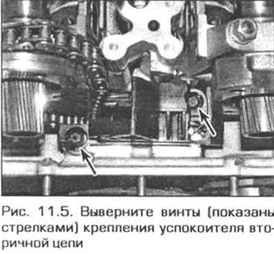
5. Unscrew the two slotted head screws and remove the secondary chain guide from the cylinder head (Fig. 11.5).
6. Remove the bolts securing the chain cover to the cylinder head.
7. Remove the thermostat as described in chapter 3.
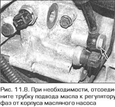
8. Remove the two bolts and disconnect the coolant pipe from the cylinder head on the intake side. For easier access, disconnect the oil supply pipe to the VANOS valve timing adjuster from the back side of the oil filter housing (Fig. 11.8). Replace the sealing washers of the fitting when installing.
9. On the left side of the cylinder head, disconnect the electrical connectors from the temperature sensor.
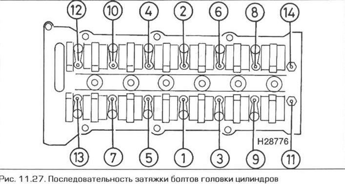
10. Gradually loosen the cylinder head bolts in the reverse order to that shown in Fig. 11.27.
11. Unscrew the bolts and take out the washers. Note that some washers may be stuck in the holes and may not be easy to remove.
12. Separate the head from the block by rocking it across the block. Do not press the head from the block with any tool, as this may damage the mating surfaces.
13. Ideally, two assistants are needed to remove the head. Ask one of them to hold the camshaft drive chain under tension. With the second assistant, lift the cylinder head and remove it from the block. As the head is lifted, have your assistant pull the chain through the opening in the head. After the head is removed, tie the chain to the block with a piece of wire.
14. Remove the cylinder head gasket.
Inspection
15. Disassembly and assembly of the cylinder head is described in chapter 2B.
16. Clean the mating surfaces of the head and block. Use a scraper to scrape off any gasket residue and carbon deposits. Clean the piston crowns as well. Be careful, especially with the head and block surfaces - aluminum parts are easily damaged. Do not allow scraped particles to enter the lubrication and cooling system passages. Seal all passages and bolt holes in the cylinder block with tape. To prevent carbon deposits from getting into the gaps between the pistons and cylinder bores, coat the gaps with consistent grease. After cleaning each piston, turn the crankshaft so that the piston goes down and wipe the grease and carbon deposits off the cylinder surface with a clean rag.
17. Inspect the block and cylinder head for scoring, deep scratches and other damage. Minor damage can be repaired with a fine file, but more serious damage requires machine processing. But this is a job for professionals.
18. If you suspect that the head is warped, check this assumption by placing the edge of a steel ruler on the surface and measuring the gap between the ruler and the surface with flat feeler gauges.
19. Clean the bolt holes in the cylinder block with a clean rag wrapped around a screwdriver. Remove all liquids from the holes, including oil, otherwise, when tightening the bolts, high pressure may be created in the closed hole, which will rupture the block.
20. Check the threads of the bolts and holes in the block for damage. Run the threads with a die and a tap of the appropriate size.
Installation
Caution: If the camshafts have been removed, observe the warning in paragraph 10 regarding extending the tappets.
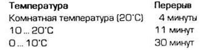
21. To prevent the valves from hitting the pistons after installing the camshafts, before returning the crankshaft to the TDC position, wait at least as long as indicated below:
22. Before installing the head on the block, their mating surfaces must be sterile clean. The bolts and bolt holes in the block must be absolutely serviceable: the bolts must be screwed in and out by hand without excessive friction or jamming. Make sure that the head mounting pins are in their places in the cylinder block.
Attention! To avoid the possibility of pistons hitting open valves when installing the cylinder head, it is necessary to move all pistons away from TDC. Before continuing assembly, turn the crankshaft to the TDC position. And check whether the lock is inserted into the flywheel), then turn the crankshaft counterclockwise by 30°.
23. Apply a thin bead of Drei Bond 1209 sealant to the mating surfaces of the chain cover and cylinder block.
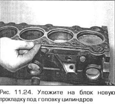
24. Place a new cylinder head gasket on the block so that the locating pins fit into the holes in the gasket (fig. 11.24). Usually the gasket has markings that define its top and bottom. Keep in mind that for a ground head a gasket of greater thickness (by 0.3 mm) is produced.
25. Place the cylinder head on the block, making sure that the locating pins fit into the holes.
26. Prepare a set of new bolts. Lubricate the bolt threads, the undersides of their heads, and the washers with engine oil. Screw the bolts into the holes and tighten them as much as possible by hand. Make sure that the washers are not warped.
Note: Do not install a washer on a bolt if there is an existing washer in the hole that could not be removed.
27. Tighten the bolts in the sequence shown in Fig. 11.27. in several stages, as specified in the Technical Data.
28. Screw in and tighten the bolts securing the chain cover to the cylinder head.
29. Install the secondary chain guide and securely attach it to the cylinder head with screws.
30. Install the camshafts and tappets as shown in paragraph 10.
31. Rotate the crankshaft 30° clockwise to return it to the TDC position. Secure the shaft in this position by inserting the locking pin into the flywheel.
32. The rest of the installation is carried out in the reverse order of removal. Finally, fill the cooling system.
The original article is available on the website BMWMan.ru
This article is available at russian, bulgarian, belarusian, ukrainian, serbian, croatian, romanian, polish, slovak, hungarian
Article verified: Ilyinsky Matvey
Share information:
Previous articles
БМВ E46: 6 cylinder engines
Next articles
Similar articles on other types of BMW cars:
Removal and installation of cylinder head — engines M20, M21, M30 BMW 5 Series E34 (1988-1996)
Removal and installation the cylinder head / replacing the cylinder… BMW 5 Series E39 (1995-2003)
Cylinder head of gasoline engines of the M52 series — removal and… BMW 7 Series E32 (1986-1994)
Removal and installation cylinder head covers BMW 7 Series E38 (1994-2001)
Removal and installation the cylinder head BMW X3 E83 (2003-2010)
Removal and installation the lock cylinder BMW X5 E53 (1999-2006)
Link in different formats to this page
Visitor comments
No comments yet
- General information
- Manual
- Maintenance
- Power unit
- Engine repair
- Cooling system
- Power system (gasoline)
- Injection system (gasoline)
- Fuel system (diesel)
- Exhaust system
- Ignition system
- Charge and launch systems
- Transmission
- Car gearbox
- Clutch and drive shafts
- Chassis
- Brake system
- Suspension front and rear
- Steering
- Body
- Body care and repair
- Exterior
- Interior
- Electrical equipment
- Troubleshooting
- Lighting and signaling
- Equipment and devices
- Heater and air conditioner
- Electrical circuits
- General information
- Manual
- Repair on the road
- Weekly checks
- Maintenance
- Troubleshooting
- Power unit
- 4 cylinder engines
- 6 cylinder engines
- Engine overhaul
- Cooling and heating
- Fuel and exhaust system
- Starting and charging system
- Ignition system
- Transmission
- Clutch
- Mechanical gearbox
- Automatic gearbox
- Cardan and drive shafts
- Chassis
- Brake system
- Wheel suspension
- Steering
- Body
- Exterior
- Interior
- Electrical equipment
- Equipment and devices
- Electrical circuits
- General information
- Maintenance
- Power unit
- Engine repair
- Cooling system
- Ignition system
- Supply system
- Fuel injection system
- Exhaust system
- Transmission
- Clutch
- Car gearbox
- Front and rear axle
- Chassis
- Steering
- Brake system
- Body
- Exterior
- Interior
- Electrical equipment
- Heating system
- Equipment and devices
- Power devices
- Electrical circuits
- Power unit
- M10/M20 engine
- M40 engine
- Ignition system
- Lubrication system
- Cooling system
- Supply system
- Fuel injection
- Exhaust system
- Transmission
- Clutch
- Manual gearbox
- Front axle
- Rear axle
- Chassis
- Steering
- Brake system
- Body
- Exterior
- Interior
- Electrical equipment
- Heating system
- Equipment and devices
- Electrical circuits
- General information
- Specifications
- Operation and maintenance
- 4-cylinder engine
- Engine repair
- Cooling and lubrication system
- Supply system
- Ignition system
- 6-cylinder engine
- Engine repair
- Cooling and lubrication system
- Supply system
- Fuel injection system
- Ignition system
- Transmission
- Clutch
- 4-speed manual gearbox
- 5-speed manual gearbox
- Automatic gearbox
- Cardan and rear axle
- Chassis
- Steering
- Front suspension
- Rear suspension
- Brake system
- Electrical equipment
- Equipment and devices
- Electrical circuits