
Table of contents: Secondary circuit ↓ Primary chain ↓
- Home
- BMW 3 Series
- E46
- Power unit
- 6 cylinder engines
- Timing chains — removal, inspection and installation
Timing chains — removal, inspection and installation (BMW 3 Series E46)
Secondary circuit
Removal
1. Remove the valve timing adjuster as described in paragraph 9.
2. On the right side of the engine, unscrew the tensioner plunger assembly (Fig. 7.2). The sealing ring can be discarded - a new one will be required for assembly.
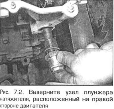
Caution! There is a tight spring in the plunger assembly. Be careful.
3. If you intend to continue using the tensioner assembly, press the plunger several times to force out any remaining oil from the assembly.
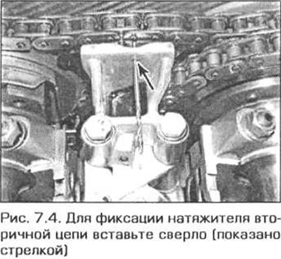
4. Press the plunger of the secondary chain tensioner and fix it in this position by inserting a drill of a suitable diameter into the hole (Fig. 7.4).
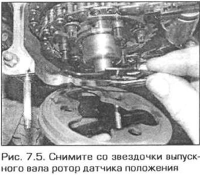
5. Loosen the nut and remove the camshaft position sensor rotor and leaf spring from the exhaust camshaft sprocket (Fig. 7.5).
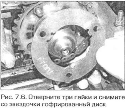
6. Unscrew the three nuts securing the intake shaft sprocket and remove the corrugated disk from the sprocket (Fig. 7.6).
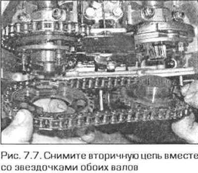
7. Remove the three screws securing the exhaust shaft sprocket and remove the secondary chain together with the sprockets (Fig. 7.7). If you intend to use these parts in the future, store them so that they will be in their original position during assembly.
Inspection
8. If the sprocket teeth or chain are worn out, the chain should be replaced. A worn chain has noticeable play in the links, the link axles have grooves at the ends. A worn chain makes noise when running. It is recommended to change the chain in any case when the engine is disassembled for major repairs. If the chain raises any suspicions, then in order to avoid further major troubles, it is better to replace it.
9. Inspect the sprocket teeth for wear. The teeth of a new sprocket look like an inverted V. When worn, a semicircular groove appears on the side surface of the working side of the tooth and the tooth takes on the shape of a hook. When the teeth are worn, the sprocket must be replaced. Also inspect the working surfaces of the tensioner shoe and chain guide for wear and replace them if necessary.
Installation
10. Make sure that piston #1 is still at TDC and that the crankshaft is locked in this position.
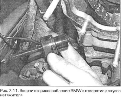
11. Make sure that the primary chain and the exhaust camshaft sprocket are in place. Screw the BMW tool 11 4 220 into the hole where the primary chain tensioner unit should be located and turn the tool screw until the screw touches the tensioner shoe (Fig. 7.11).
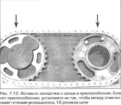
12. To set the correct mutual arrangement of the two sprockets, use the BMW 116 180 device. Insert both sprockets into the chain and place everything together in the device. If there is no device, install the sprockets so that 16 chain rollers fit between the marked points (Fig. 7.12).
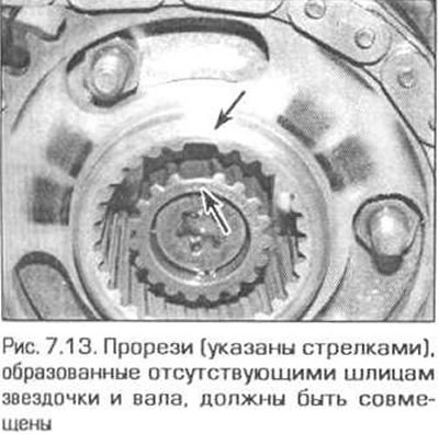
13. Place the sprockets on the ends of the camshafts so that the slots on the sprocket and intake shaft sprocket surfaces align (Fig. 7.13).
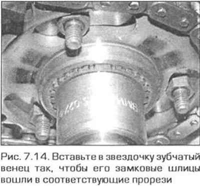
14. Insert the toothed ring into the intake camshaft sprocket so that its locking splines enter the corresponding slots in the sprocket and shaft (Fig. 7.14). Push the toothed ring into the sprocket so that approximately 1 mm of the ring remains visible.
15. Install the corrugated disc onto the intake shaft sprocket with the FRONT mark facing forward. Install the nuts, but tighten them only by hand.
16. Screw the screws into the exhaust shaft sprocket, tighten them to 5 Nm, then unscrew them 180°.
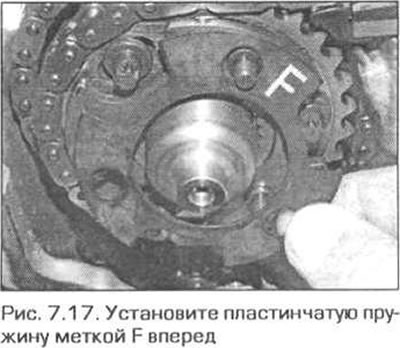
17. Install the friction disc and leaf spring onto the exhaust shaft sprocket with the F mark facing forward. If the mark is not visible, install the leaf spring with the convex side facing forward (Fig. 7.17).
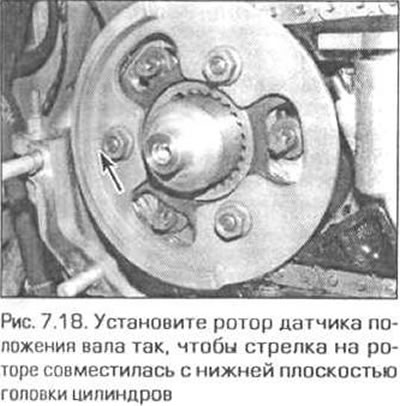
18. Install the rotor of the shaft position sensor on the exhaust shaft so that the arrow on the rotor coincides with the plane of the cylinder head under the gasket (Fig. 7.18). Screw on the nuts and tighten them by hand for now.
19. Pull the ring gear out of the exhaust shaft as far as possible.
20. Press the secondary target tensioner plunger and pull out the locking rod (or a drill).
21. Using a torque wrench, tighten the adjusting screw on the fixture screwed into the hole for the primary chain tensioner assembly to 0.7 Nm. If you do not have a suitable torque wrench, tighten the screw enough to remove all slack in the chain. Check that the slack has been removed by trying to turn the exhaust shaft sprocket by hand.
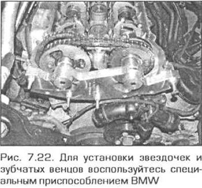
22. To check the correct alignment of the sprockets, install the BMW 116150 device in place of the valve timing adjuster. Install the device on the valve timing adjuster studs (without gasket) and tighten the nuts evenly so that the device completely touches the cylinder head. This device sets the position of the toothed rims and holds them while tightening the bolts/nuts of the sprockets (Fig. 7.22). Without this device it is impossible to set the initial phases of the camshafts, so its use is mandatory.
23. Gradually and evenly tighten the sprocket nuts/bolts to the torque corresponding to stage 1 (see Technical data). First tighten the slotted head cap screws of the exhaust shaft sprocket, then the nuts of the same sprocket, then tighten the nuts of the intake shaft sprocket. In the same sequence, tighten first the screws and then the nuts to the 2nd stage torque. After tightening the fasteners, without removing the 116 150 tool, remove the flywheel lock and the templates that lock the camshafts. Turn the crankshaft two full turns and reinsert the lock into the flywheel.
24. Check the position of the camshafts by inserting templates, make sure that the shafts are positioned correctly.
Note. Due to the rubberized sprockets and tolerances in the connections, there may be a misalignment of the inlet shaft locking device with the square flange of up to 1 mm. The relative position of the shafts should be considered satisfactory.
25. Remove tool 11 6 150 and install the phase regulator in place (see paragraph 9).
Primary chain
Removal
26. Remove the secondary chain as described in the previous paragraph.
27. Remove the toothed ring from the exhaust shaft sprocket and remove the flange with internal splines from it.
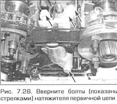
28. Unscrew the four bolts and remove the primary chain tensioner (Fig. 7.28).
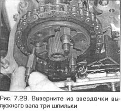
29. Remove three studs from the output shaft sprocket (Fig. 7.29), lift the chain and remove the sprocket from the shaft. Note which side the sprocket is installed facing outward.
30. Remove the chain cover as described in paragraph 6.
31. Remember the chain routing relative to the tensioner and guide.
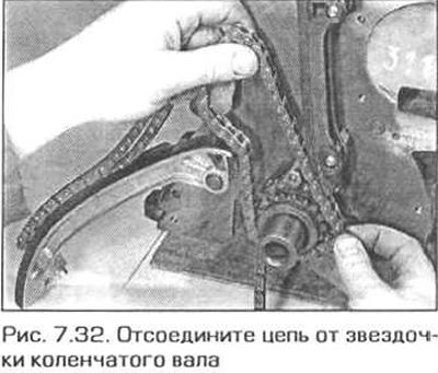
32. Disconnect the chain from the crankshaft sprocket and pull it out of the engine. If the chain shoe is in the way, move it as necessary (Fig. 7.32).
Caution! After removing the chain, do not turn the crankshaft or camshafts, as this can cause the pistons to hit the valves.
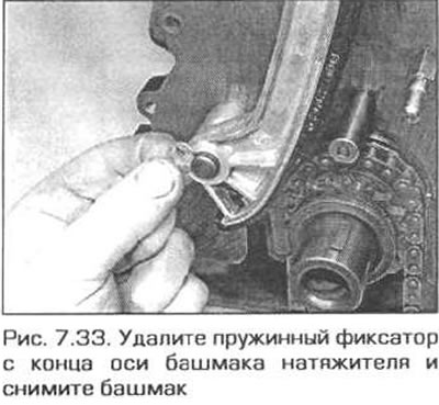
33. If necessary, you can now remove the tensioner shoe. To do this, remove the spring clip from the end of its axle (Fig. 7.33).
34. The chain guide can be removed in the same way, for which you need to remove the upper and lower spring clamps. Be careful - the clamps are fragile and can be easily damaged (Fig. 7.34).

Installation
35. Make sure that piston No.1 is at TDC at the end of the compression stroke and that the crankshaft is locked in this position. Using a template, also check the position of the camshafts.
36. Place the chain on the crankshaft sprocket.
37. Install the tensioner shoe and chain guide in place (if they were removed). Route the chain relative to the tensioner and the guide as before disassembly. Secure the shoe and guide with spring clamps. Be careful - the clamps are easily damaged.
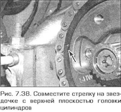
38. Turn the exhaust camshaft sprocket so that the arrow on the sprocket is aligned with the upper plane of the cylinder head, and place the chain on the sprocket (Fig. 7.38). Then place the sprocket on the shaft.
39. Install the chain cover as described in paragraph 6.
40. Screw the tool 11 4 220 into the hole for the tensioner unit (see paragraph 9) and rotate the adjusting screw of the device until its ends touch the tensioner shoe. In this case, the sprocket of the exhaust shaft may turn slightly. If necessary, reinstall the sprocket relative to the chain so that the arrow on the sprocket is still aligned with the upper plane of the cylinder head.
41. Screw three studs into the sprocket and tighten them to the required torque.
42. Install the secondary chain tensioner and tighten its bolts securely.
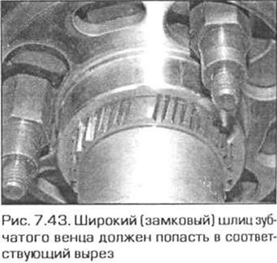
43. Install a flange with internal splines on the sprocket so that the cutout in the flange formed by the missing spline aligns with the same cutout on the splined end of the shaft. Insert the ring gear into the flange so that its locking (wide) splines fit into the corresponding cutouts in the flange and on the end of the shaft (Fig. 7.43).
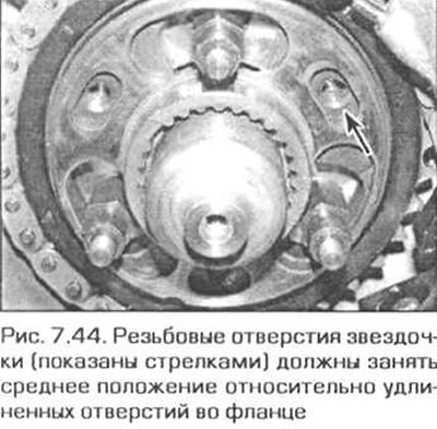
44. Push the ring gear so that the threaded holes in the sprocket occupy a middle position relative to the elongated holes in the flange (Fig. 7.44).
45. Install the chain as specified in items 10-25 of this paragraph.
The text is based on materials from the website: «BMWMAN.ru»
This article is available at russian, bulgarian, belarusian, ukrainian, serbian, croatian, romanian, polish, slovak, hungarian
Article verified: Ilyinsky Matvey
Share information:
Previous articles
БМВ E46: 6 cylinder engines
Next articles
Similar articles on other types of BMW cars:
Removal, inspection and installation of the timing belt and its… BMW 5 Series E28 (1981-1988)
Removal and installation, inspection of the rear shock absorber BMW 5 Series E34 (1988-1996)
Timing Chain Covers — Removal and Installation BMW 7 Series E32 (1986-1994)
Removal and installation the cylinder head, adjusting the timing… BMW 7 Series E38 (1994-2001)
Pistons — removal and installation BMW X3 E83 (2003-2010)
Removal and installation the engine BMW X5 E53 (1999-2006)
Link in different formats to this page
Visitor comments
No comments yet
- General information
- Manual
- Maintenance
- Power unit
- Engine repair
- Cooling system
- Power system (gasoline)
- Injection system (gasoline)
- Fuel system (diesel)
- Exhaust system
- Ignition system
- Charge and launch systems
- Transmission
- Car gearbox
- Clutch and drive shafts
- Chassis
- Brake system
- Suspension front and rear
- Steering
- Body
- Body care and repair
- Exterior
- Interior
- Electrical equipment
- Troubleshooting
- Lighting and signaling
- Equipment and devices
- Heater and air conditioner
- Electrical circuits
- General information
- Manual
- Repair on the road
- Weekly checks
- Maintenance
- Troubleshooting
- Power unit
- 4 cylinder engines
- 6 cylinder engines
- Engine overhaul
- Cooling and heating
- Fuel and exhaust system
- Starting and charging system
- Ignition system
- Transmission
- Clutch
- Mechanical gearbox
- Automatic gearbox
- Cardan and drive shafts
- Chassis
- Brake system
- Wheel suspension
- Steering
- Body
- Exterior
- Interior
- Electrical equipment
- Equipment and devices
- Electrical circuits
- General information
- Maintenance
- Power unit
- Engine repair
- Cooling system
- Ignition system
- Supply system
- Fuel injection system
- Exhaust system
- Transmission
- Clutch
- Car gearbox
- Front and rear axle
- Chassis
- Steering
- Brake system
- Body
- Exterior
- Interior
- Electrical equipment
- Heating system
- Equipment and devices
- Power devices
- Electrical circuits
- Power unit
- M10/M20 engine
- M40 engine
- Ignition system
- Lubrication system
- Cooling system
- Supply system
- Fuel injection
- Exhaust system
- Transmission
- Clutch
- Manual gearbox
- Front axle
- Rear axle
- Chassis
- Steering
- Brake system
- Body
- Exterior
- Interior
- Electrical equipment
- Heating system
- Equipment and devices
- Electrical circuits
- General information
- Specifications
- Operation and maintenance
- 4-cylinder engine
- Engine repair
- Cooling and lubrication system
- Supply system
- Ignition system
- 6-cylinder engine
- Engine repair
- Cooling and lubrication system
- Supply system
- Fuel injection system
- Ignition system
- Transmission
- Clutch
- 4-speed manual gearbox
- 5-speed manual gearbox
- Automatic gearbox
- Cardan and rear axle
- Chassis
- Steering
- Front suspension
- Rear suspension
- Brake system
- Electrical equipment
- Equipment and devices
- Electrical circuits