
- Home
- BMW 3 Series
- E46
- Power unit
- 6 cylinder engines
- Camshafts and tappets — removal, inspection and installation
Camshafts and tappets — removal, inspection and installation (BMW 3 Series E46)
Attention! To perform this operation, you will need the BMW 113 360 tool. It is extremely difficult to make such a tool yourself due to its complex design and high manufacturing precision requirements. Do not attempt to remove the camshafts without this tool, as this may cause damage that will require expensive repairs.
Removal
1. Remove the VANOS regulator as described in the previous paragraph.
2. Remove the secondary timing chain as described in paragraph 7.
3. Remove the flange and ring gear from the exhaust camshaft sprocket.
4. Remove the secondary target tensioner (see fig. 8.13).
5. Remove the three studs from the exhaust shaft sprocket, lift the chain and remove the sprocket from the end of the shaft. Note which side the sprocket is installed facing outward.
6. Remove the locking pin from the flywheel, then, keeping the primary chain taut, rotate the crankshaft 30° counterclockwise to prevent the pistons from accidentally hitting open valves. Use a piece of wire to tie the primary chain to the cylinder head so that it does not fall into the engine and become uncoupled from the sprocket.
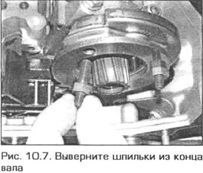
7. If necessary, unscrew the studs from the end of the intake shaft and remove the shaft position sensor rotor (Fig. 10.7)
8. Remove the timing template from the camshafts.
9. Remove the spark plugs.
10. Check for pi markings on the camshaft caps. The caps should be numbered starting from the front of the engine and the numbers should be easy to read from the exhaust side. Exhaust caps are marked A1 through A7, and intake caps are marked E1 through E7.
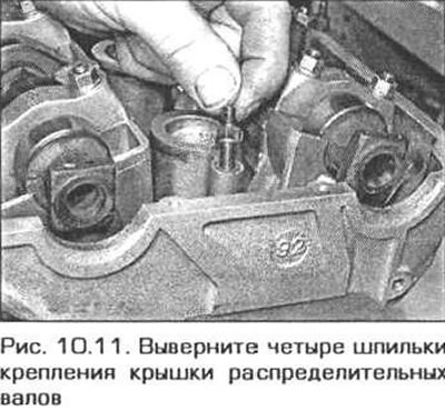
11. Remove the four camshaft cover mounting studs from the cylinder head (fig. 10.11).
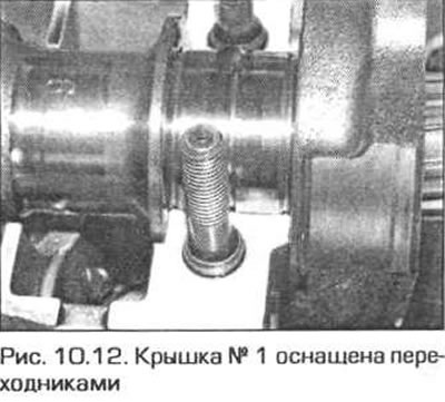
12. Unscrew the nuts of cover No.1 and remove the cover so that it does not jam when removing the shaft (fig. 10.12).
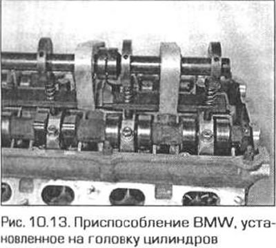
13. The shafts are removed one by one. Install the device 11 3 260 on the cylinder head. Screw its bolts into the spark plug holes. Install the device so that the plungers are located above the covers of the corresponding shaft (i.e. inlet or outlet) (fig. 10.13).
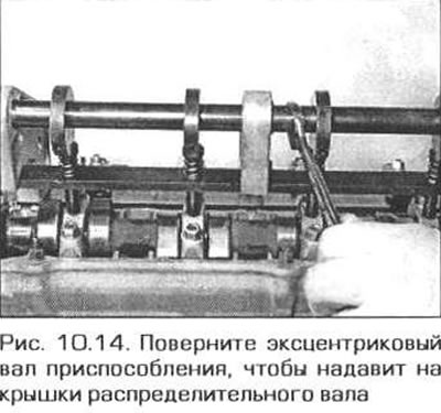
14. Turn the eccentric shaft of the device with a key by its flats to press on the camshaft covers (fig. 10.14).
15. Unscrew the nuts of the remaining covers.
Caution! Do not unscrew the cap nuts without a tool - you can damage the camshaft or its supports.
16. Relieve the pressure from the caps and remove the tool from the cylinder head.
17. Remove the bearing caps, then lift the camshaft. Store the bearing caps so that they return to their original positions when reassembled.
18. Now you can remove the bearing block from the cylinder head. The bearing block must be removed very slowly, since the tappets will be released when the support is raised and may jump out of their sockets. The danger is that the tappets may move and it will be impossible to install them in their original places later.
19. After removing the support block, pull out the valve lifters one by one. Lay out the lifters in a certain sequence that will allow you to install them in their original places. Store the lifters in a vertical position in containers filled with oil.
20. To remove the second camshaft, repeat the same steps.
Inspection
21. Clean and wash all parts, including the shaft bearings and their covers. Inspect the parts for wear and damage. Pay particular attention to the bearings and cam surfaces for chips and pitting. Also inspect the tappet surfaces for wear and scoring. Replace any parts with defects.
Installation
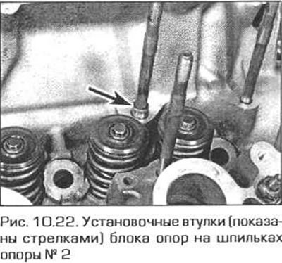
22. If the camshaft bearing blocks have been removed, check whether the mating surfaces of the bearings and the cylinder head are clean enough. Check whether the installation bushings, which should be located on the studs of bearings No.2 and 7, are in place (fig. 10.22).
23. Install the support blocks and valve lifters in their places.
24. The simplest thing is to secure the pushers in the support and install them in place as an assembly.
25. Lubricate the tappet bores in the shaft support block with engine oil (do not lubricate the end surfaces of the pushers yet) and insert the pushers and the support block into their original places.
26. After installing all the tappets in the support block, the tappets must be secured in the block so that they do not fall out of it when installing the support block on the cylinder head.
27. Install the bearing block with tappets on the cylinder head. Note: the bearing block of the intake shaft is marked A, and the bearing block of the exhaust shaft is marked E. After installing the bearing blocks, the shaft markings should be on the primary chain side and facing each other.
Caution! Valve tappets that are not loaded by the cam force may increase in length. If the camshaft is installed quickly, there is a risk that the closed valves will go down under the action of the elongated tappets and hit the pistons.
28. To prevent the valves from hitting the pistons after installing the camshafts, before returning the crankshaft to the TDC position, wait at least as long as indicated below:

29. First, identify the shafts so that they are not mixed up. The intake shaft has a triangular flange at the front end, and the exhaust shaft has a round flange. Make sure that the crankshaft is still turned 30° counterclockwise from TDC.
30. Place the camshafts in the supports so that the front cams of the intake and exhaust shafts are directed towards each other. The sides of the square flanges on the rear ends of the shafts must be strictly perpendicular to the upper plane of the cylinder head (you can check with a square), and the side of the flange with the holes should be on top. After installing the exhaust shaft, put the primary chain on its front end.
31. Install the camshaft bearing caps in their places in accordance with their markings. The exhaust camshaft caps are marked from A1 to A7, and the intake camshaft caps are marked from E1 to E7.
32. Place tool 11 3 260 on top of the covers and secure it to the cylinder head as during disassembly.
Caution: Do not attempt to complete installation of the camshafts without this tool.
33. Press the covers of the corresponding shaft by turning the eccentric shaft of the device.
34. After pressing the covers, screw on the cover fastening nuts and tighten them by hand as much as possible.
35. Tighten the support cap nuts to the specified torque in a diagonal sequence.
36. After tightening all the nuts, unscrew and remove the cap pressing device.
37. Install the second shaft in the same way.
38. Screw in the spark plugs and camshaft cover studs.
39. Insert the template to check the installation of the camshafts. If necessary, turn the shafts by the flats on them until the template is in place.
Warning! Before continuing, read the warning after item 27.
40. Turn the crankshaft 30° clockwise to the TDC position and insert the flywheel lock.
41. Install the camshaft sprockets and timing chains as described in paragraph 7.
42. Install the VANOS phase adjuster unit as described in paragraph 9.
43. To prevent the valves from hitting the pistons after installing the camshafts, before turning the crankshaft with the starter, make a break of at least the length specified below:

This article is available at russian, bulgarian, belarusian, ukrainian, serbian, croatian, romanian, polish, slovak, hungarian
Article verified: Ilyinsky Matvey
Share information:
Previous articles
БМВ E46: 6 cylinder engines
Next articles
Valve timing control (VANOS) components — removal, inspection and…
Sprockets and chain tensioners — removal, inspection and installation
Timing chains — removal, inspection and installation
Timing Chain Cover — Removal and Installation
Crankshaft pulley and vibration damper — removal and installation
Sprockets and chain tensioners — removal, inspection and installation
Timing chains — removal, inspection and installation
Timing Chain Cover — Removal and Installation
Crankshaft pulley and vibration damper — removal and installation
Similar articles on other types of BMW cars:
Removal and installation, inspection of the rear shock absorber BMW 5 Series E34 (1988-1996)
Removal, inspection and installation of the timing belt and its… BMW 5 Series E28 (1981-1988)
Drive chain and sprockets — removal, inspection and installation BMW 7 Series E32 (1986-1994)
Removal and installation of cylinder heads, camshafts and their… BMW 7 Series E38 (1994-2001)
Pistons — removal and installation BMW X3 E83 (2003-2010)
Removal and installation the engine BMW X5 E53 (1999-2006)
Link in different formats to this page
Visitor comments
No comments yet
- General information
- Manual
- Maintenance
- Power unit
- Engine repair
- Cooling system
- Power system (gasoline)
- Injection system (gasoline)
- Fuel system (diesel)
- Exhaust system
- Ignition system
- Charge and launch systems
- Transmission
- Car gearbox
- Clutch and drive shafts
- Chassis
- Brake system
- Suspension front and rear
- Steering
- Body
- Body care and repair
- Exterior
- Interior
- Electrical equipment
- Troubleshooting
- Lighting and signaling
- Equipment and devices
- Heater and air conditioner
- Electrical circuits
- General information
- Manual
- Repair on the road
- Weekly checks
- Maintenance
- Troubleshooting
- Power unit
- 4 cylinder engines
- 6 cylinder engines
- Engine overhaul
- Cooling and heating
- Fuel and exhaust system
- Starting and charging system
- Ignition system
- Transmission
- Clutch
- Mechanical gearbox
- Automatic gearbox
- Cardan and drive shafts
- Chassis
- Brake system
- Wheel suspension
- Steering
- Body
- Exterior
- Interior
- Electrical equipment
- Equipment and devices
- Electrical circuits
- General information
- Maintenance
- Power unit
- Engine repair
- Cooling system
- Ignition system
- Supply system
- Fuel injection system
- Exhaust system
- Transmission
- Clutch
- Car gearbox
- Front and rear axle
- Chassis
- Steering
- Brake system
- Body
- Exterior
- Interior
- Electrical equipment
- Heating system
- Equipment and devices
- Power devices
- Electrical circuits
- Power unit
- M10/M20 engine
- M40 engine
- Ignition system
- Lubrication system
- Cooling system
- Supply system
- Fuel injection
- Exhaust system
- Transmission
- Clutch
- Manual gearbox
- Front axle
- Rear axle
- Chassis
- Steering
- Brake system
- Body
- Exterior
- Interior
- Electrical equipment
- Heating system
- Equipment and devices
- Electrical circuits
- General information
- Specifications
- Operation and maintenance
- 4-cylinder engine
- Engine repair
- Cooling and lubrication system
- Supply system
- Ignition system
- 6-cylinder engine
- Engine repair
- Cooling and lubrication system
- Supply system
- Fuel injection system
- Ignition system
- Transmission
- Clutch
- 4-speed manual gearbox
- 5-speed manual gearbox
- Automatic gearbox
- Cardan and rear axle
- Chassis
- Steering
- Front suspension
- Rear suspension
- Brake system
- Electrical equipment
- Equipment and devices
- Electrical circuits