
Oil pump
Note. During installation, it will be necessary to replace the O-rings of the oil pick-up pipe and plugs of the pressure reducing valve, as well as the spring ring of the pressure reducing valve.
Removal and installation
1. Remove the sump as described in the previous paragraph.
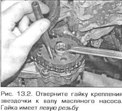
2. Loosen the nut securing the sprocket to the pump shaft. Please note that the nut has a left-hand thread (pic. 13.2).
3. Remove the sprocket and chain from the pump shaft.
4. On models where the pump is combined with an oil damper, unscrew the bolts and remove the damper along with the pump and oil pickup pipe.
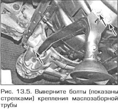
5. On models where the oil pump and damper are made separately, unscrew the two bolts securing the oil intake pipe to the oil damper and one bolt securing the pipe to the pump (pic. 13.5). Remove the pipe.
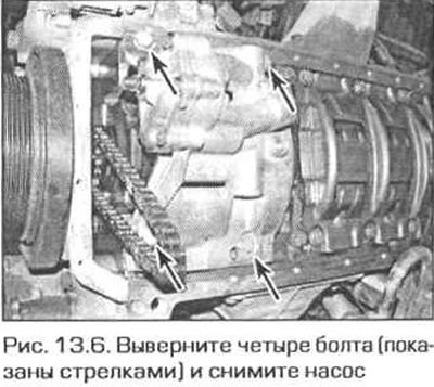
6. Turn out four bolts of fastening of the pump and remove the pump from the engine (pic. 13.6).
Inspection
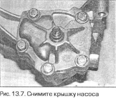
7. Turn out bolts of a cover of the pump and remove a cover (pic. 13.7).
8. Remove the rotors from the pump.
9. Inspect the pump housing, cover, and rotors for wear, nicks, and cracks. If any defects are evident, replace the rotors or pump assembly depending on the severity of the defect. It is recommended to replace the entire pump.
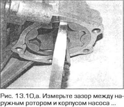
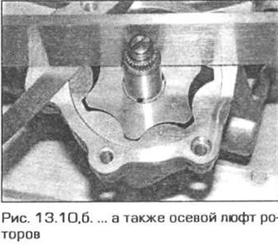
10. Insert the rotors into the pump housing and use a feeler gauge to measure the clearance between the outer rotor and the housing. Place a steel ruler edgewise on the pump housing and use feeler gauges to measure the gap between the ruler and each of the rotors (those. axial play of the rotors in the housing) (pic. 13.10, a, b). Compare the results with the Technical Data and, if necessary, replace worn parts or the entire pump.
11. To disassemble the pressure reducing valve, lightly press the valve into the body with some metal tool and remove the spring ring from the upper part of the body (pic. 13.11).
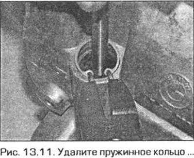
Attention! The valve has a tight spring. Be careful when you remove the snap ring.
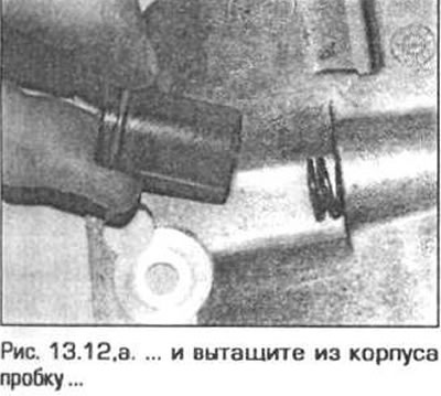
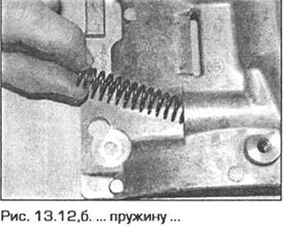
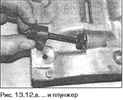
12. Remove the plug, spring and plug from the valve body (pic. 13.12, a-c).
13. Put a new sealing ring on the valve plug, then assemble the valve in the reverse order of disassembly. Secure the valve parts with a new circlip.
14. Insert the rotors into the pump housing, then install the cover, screw in the bolts and tighten them to the required torque.
15. Otherwise, the pump is installed in the reverse order of removal, taking into account the following remarks.
- A) Replace the oil pickup pipe O-ring.
- b) Tighten the pump sprocket nut (with left hand thread) the required moment.
Oil pump drive chain
Withdrawal
16. Remove the primary camshaft drive chain (see paragraph 7).
17. Remove the oil pump chain from the crankshaft sprocket.
Inspection
18. Perform the operations described in paragraph 7 for the secondary chain of the camshafts.
Installation
19. Put the chain on the crankshaft sprocket, then install the primary chain as indicated in paragraph 7.