
Table of contents: Removal ↓ Installation ↓
- Home
- BMW 7 Series
- E38
- Power unit
- Engine M60/1, M60/2 (petrol)
- Removal and installation the cylinder head, adjusting the timing phases
Removal and installation the cylinder head, adjusting the timing phases (BMW 7 Series E38)
Removal
1. Remove the appropriate exhaust manifold (see section Removal and installation of exhaust manifolds).
2. Drain the engine cooling system (see chapter Vehicle settings and routine maintenance).
3. Remove the covers of both cylinder heads (see section Petrol engines M60/1 and M60/2).
4. Remove the spark plugs (see chapter Vehicle settings and routine maintenance).
5. When removing the right cylinder head, remove the engine cooling fan clutch (see section Removal and installation the fan drive clutch Chapters Engine cooling, heating, ventilation and air conditioning systems).
6. Remove the engine cooling system manifold (see section Removal and installation the cooling system manifold Chapters Engine cooling, heating, ventilation and air conditioning systems).
7. Remove the oil supply channels from both cylinder heads.
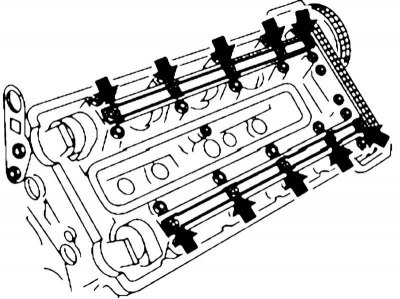
8. Turn the crankshaft clockwise by the central bolt so that the piston of the first cylinder is at the TDC of the end of the exhaust stroke. Then loosen the three accessible bolts securing the camshaft sprockets of the opposite cylinder head by half a turn.
Fasteners for camshaft sprockets of the right cylinder head (piston of the 1st cylinder at TDC of the exhaust stroke)
9. Turn the crankshaft so that the piston of the first cylinder is at TDC at the end of the compression stroke.
10. Holding the camshaft with a wrench by the hexagon, loosen the remaining bolts securing the camshaft sprockets of the opposite cylinder head by about half a turn.
11. Remove the chain tensioner plunger and remove the corresponding upper timing belt cover (see section Removal and installation timing chain covers).
12. On the appropriate cylinder head, remove the intake camshaft sprocket. Secure the chain to prevent it from slipping.
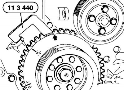
13. Turn the crankshaft counterclockwise to the 45° TDC position in accordance with the timing marks.
On engines without a 45° mark, the shaft should be turned until tool #11 3 440 fits into the recess on the CKP sensor rotor.
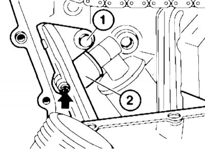
14. When removing left cylinder heads, unscrew the countersunk screw and, if equipped, the bolt (1) securing the angular coupling (2).
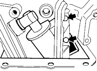
15. Unscrew the chain guide mounting bolt, and when removing left cylinder heads additionally PCV oil separator bolts. When removing the left cylinder head, remove the oil separator from the angular coupling.
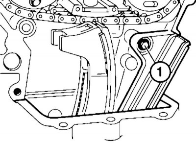
Chain guide mounting bolts on the right cylinder head
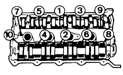
16. Unscrew the cylinder head mounting bolts reverse sequences.
17. Remove the cylinder head, clean the surfaces mating with the cylinder block from gasket and sealant residues. Try not to damage the mating surfaces, and do not allow dirt and oil to get into the threaded holes. Clean the threaded holes if necessary.
Installation
1. Apply Hylomar SQ 32 M grease to the joint between the cylinder block and the timing belt cover.
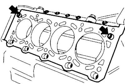
2. Make sure that the centering bushings are intact and correctly installed and place them on the cylinder block new gasket.

3. Install the cylinder head and tighten its mounting bolts to the required force and sequence.
When installing the left cylinder head, the oil separator should be pressed outward. Make sure that the oil drain pipe is connected correctly to the oil separator.
4. When installing left cylinder heads, install the oil separator into the angle bracket, after checking the condition of the sealing ring and replacing it if necessary.
5. Tighten the timing chain guide mounting bolts.
6. When installing left cylinder heads, tighten the oil separator fastener and the countersunk screw.
At this stage, the screw should be tightened until it fits against the corner coupling.
7. Using a wrench, center the camshafts.
8. Install on camshafts right cylinder heads with devices No.11 2 445/441, and on the shafts of the left head – devices No.11 2 446/442.
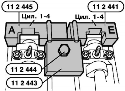
Special devices on the right cylinder head
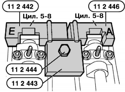
Special devices on the left cylinder head
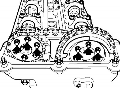
9. In the position of the piston of the first cylinder at TDC at the end of the compression stroke, the installation holes of camshafts 1 and 2, as well as 3 and 4 (right bank of cylinders) are located at the top.
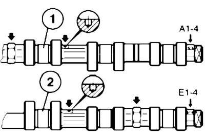
Marks on the shafts of the right cylinder head
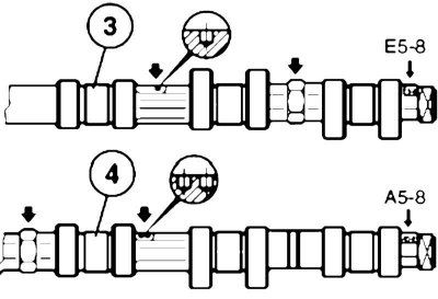
Marks on the shafts of the left cylinder head
10. Secure the camshafts with a wrench so that the fixtures fit against the cylinder head without gaps.
11. Install tool No.11 2 443 on both cylinder heads and secure it with bolt No.11 2 444.
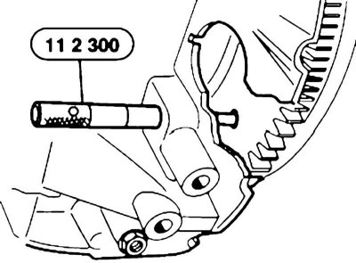
12. Turn the crankshaft clockwise from the 45° BTDC position to the TDC position and lock the shaft in this position using special tool No.11 2 300 or a suitable rod.
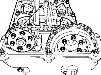
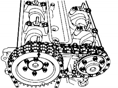
13. Install the sprocket with chain on the intake camshaft of the cylinder head being installed so that the arrow on the cylinder axis points upwards and the mounting bolts are in the middle of the longitudinal grooves. Screw in the bolts by hand.
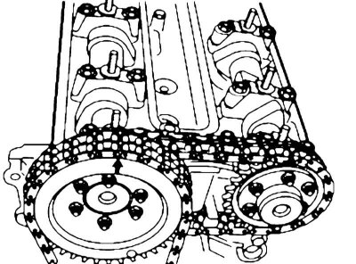
Installing the left cylinder head intake camshaft sprocket
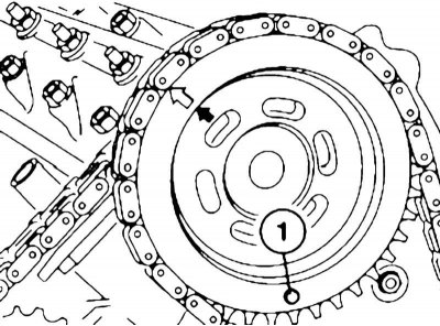
Installing the right cylinder head intake camshaft sprocket
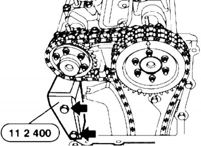
14. When installing right install tool No.11 2 400 on the cylinder head.
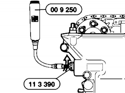
15. Insert into the right timing belt cover (when installing the left cylinder head) or for device No.11 2 400 (when installing the right cylinder head) tool No.11 3 390 and, turning the adjusting screw on it using special tool No.00 9 250, tighten the tensioner bar with a force of 1.3 Nm.
16. Tighten to the specified torque: all left exhaust camshaft bolts, 3 right exhaust camshaft bolts, all left intake camshaft bolts, and finally 3 right intake camshaft bolts.
17. Remove tools No.11 2 444/443/441/445/442/446, as well as the crankshaft locking tool.
18. Turn the crankshaft one revolution and tighten the 3 remaining bolts securing the right camshaft sprockets.
19. Install the oil supply channels.
20. Remove the tensioner bar tightening tools.
21. Install the remaining removed components in the reverse order of their removal.
This article is available at russian, bulgarian, belarusian, ukrainian, serbian, croatian, romanian, polish, slovak, hungarian
Article verified: Polikarpov Saveliy
Share information:
Previous articles
БМВ E38: Engine M60/1, M60/2 (petrol)
Next articles
Similar articles on other types of BMW cars:
Removal and installation the cylinder head BMW 3 Series E30 (1982-1994)
Removal and installation the cylinder head. Models 318is, 318ti BMW 3 Series E36 (1990-2000)
Removal and installation of cylinder head — engines M20, M21, M30 BMW 5 Series E34 (1988-1996)
Removal and installation the cylinder head / replacing the cylinder… BMW 5 Series E39 (1995-2003)
Removal and installation the cylinder head BMW X3 E83 (2003-2010)
Adjusting the valve timing of the right cylinder head BMW X5 E53 (1999-2006)
Link in different formats to this page
Visitor comments
No comments yet
- General information
- Introduction to guide
- Manual
- Maintenance
- Power unit
- Engine M60/1, M60/2 (petrol)
- M62 engine (petrol)
- M57 engine (diesel)
- M67 engine (diesel)
- Cooling system
- Fuel system (petrol)
- Fuel system (diesel)
- Exhaust system
- Ignition and control systems
- Charge and launch systems
- Transmission
- Clutch
- Mechanical gearbox
- Automatic gearbox
- Cardan and drive shafts
- Chassis
- Brake system
- Front suspension
- Rear suspension
- Steering
- Body
- Exterior
- Interior
- Electrical equipment
- Equipment and devices
- Lighting
- Heating and air conditioning
- Electrical circuits
- General information
- Care and maintenance
- Power unit
- Minor engine repair
- Engine overhaul
- Lubrication system
- Cooling system
- Ignition system
- Supply system
- Injection system (petrol)
- Injection system (diesel)
- Exhaust system
- Transmission
- Clutch
- Manual gearbox
- Automatic gearbox
- Cardan gear
- Rear axle and shafts
- Chassis
- Front suspension
- Rear suspension
- Steering
- Wheels and tires
- Brake system
- Body
- Body elements
- Electrical equipment
- Equipment and devices
- Electrical circuits