
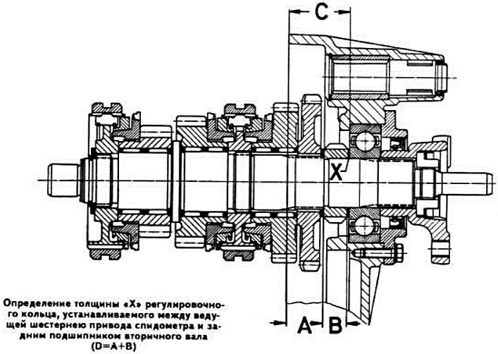
Determining the thickness of the adjusting ring installed between the speedometer drive pinion and the secondary shaft rear bearing
Measure the distance "C" between the end face of the secondary shaft rear bearing pressed into the socket of the gearbox rear cover and the parting plane of the rear cover without a sealing gasket.
Using the formula D=A+B, determine the distance between the rear end of the speedometer drive pinion and the parting plane of the rear cover without a sealing gasket, where:
- D — distance between the rear end of the speedometer drive pinion and the joint plane of the rear cover without a sealing gasket;
- A — the distance between the front end of the speedometer drive pinion and the joint plane of the rear cover without a sealing gasket, equal to 22 mm;
- B is the thickness of the speedometer drive pinion.
Using the formula X=CD, determine the thickness of the adjusting ring installed between the speedometer drive pinion and the secondary shaft rear bearing, where:
- X — thickness of the adjusting ring;
- C — distance between the end face of the secondary shaft rear bearing and the parting plane of the rear cover without a sealing gasket;
- D — the distance between the rear end of the speedometer drive pinion and the joint plane of the rear cover without the sealing gasket.
Determining the thickness of the adjusting ring installed on the front bearing of the primary shaft
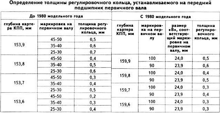
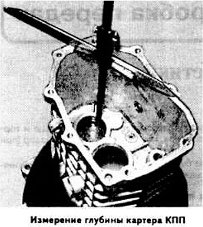
Press the front bearing of the primary shaft into the gearbox housing socket, placing a 1 mm thick ring on the clutch side. Measure the depth of the gearbox housing, i.e. the distance between the mating surface of the gearbox housing and the end of the bearing. Determine the thickness of the adjusting ring based on the obtained value and the marking on the primary shaft (see photo).
Install the selected adjusting ring on the primary shaft and press the front shaft bearing out of the gearbox housing socket.
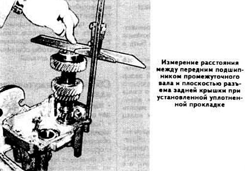
Determining the thickness of the adjusting ring installed on the rear bearing of the intermediate shaft
Measure the distance between the mating surface of the transmission housing and the intermediate shaft bearing retaining ring.
Insert the intermediate shaft with pressed bearings into the rear cover of the gearbox and measure the distance between the parting plane of the rear cover with the installed sealing gasket and the front bearing of the intermediate shaft.
The difference between the measurement results will be equal to the thickness of the adjusting rings. If it is equal to or greater than 0.4 mm, install adjusting rings at both ends of the intermediate shaft.
On vehicles from model year 1978
Measure the distance between the mating surface of the transmission housing and the bearing retaining ring.
Measure the distance between the mating surface of the gearbox rear cover and the bearing seat.
Add up the measurement results and add to them the thickness of the rear cover sealing gasket, which is 0.2 mm.
Subtract from the obtained value the length of the intermediate shaft, measured between the ends of the bearings, and the value of the maximum axial clearance of the intermediate shaft, equal to 0.2 mm, thereby determining the thickness of the adjusting ring.
Assemble the gearbox in the reverse order of disassembly. When doing so, keep the following in mind:
- after installing the reverse gear fork rod retainer ball into the rear cover, install the axle with the reverse gear intermediate gear;
- install the shafts into the rear cover in the following order: intermediate shaft, primary and secondary shaft assemblies; in this case, the bearings should enter the cover sockets until they stop;
- after installing the shafts in the rear cover, measure the recession of the secondary shaft rear bearing in the rear cover, i.e. the distance between the cover parting plane and the bearing separator. Install the seal on the bearing and measure the height of the flange. The difference between the measurement results gives the thickness of the adjusting rings to be installed;
- on vehicles from 1978 onwards, install the detent ball, reverse fork rod and reverse gear lever;
- after installing the flange on the secondary shaft, tighten the nut, having previously applied a sealant such as Loctite to the threads, and lock it by bending the plate washer;
- to facilitate pressing in the front bearing of the intermediate shaft, the gearbox housing should be heated,
- when connecting the gearbox housing to the rear cover, screw in two mounting bolts and insert the mounting pins into the sockets, then tighten the mounting bolts crosswise;
- after connecting the gearbox housing to the rear cover, press the front bearing of the primary shaft into the gearbox housing socket using the 23 1000 mandrel and install the adjusting rings and the retaining ring;
- after pressing in the front shaft bearing, measure the recession of the bearing separator relative to the plane of the gearbox housing. Measure the height of the flange on the guide sleeve of the clutch release bearing. The difference in the measurement results determines the thickness of the adjusting rings to be installed;
- before installing the front crankcase cover, apply a sealant such as Curil K2 to the mating surfaces;
- after finishing the work, fill the gearbox housing with oil.