
- Home
- BMW 3 Series
- E46
- Chassis
- Wheel suspension
- Lower control arm front suspension — removal, repair and installation
Lower control arm front suspension — removal, repair and installation (BMW 3 Series E46)
Note: You will need new lower control arm front ball joint nuts for installation.
Removal
1. Chock the rear wheels. Apply the parking brake. Raise the front of the vehicle and support it on stands (see "Lifting and installing the car on supports"). Remove the corresponding wheel.
2. Loosen the screws and remove the engine crankcase guard.
3. Unscrew the bolts and remove the cross member from under the vehicle (see chapter 2A).
4. On models with axle load sensors, loosen the nut and remove the tie rod bracket from the lower arm.
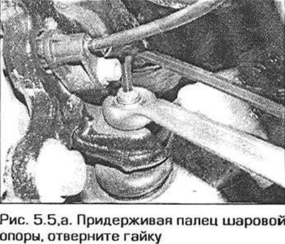
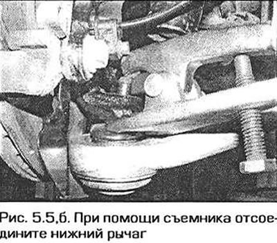
5. Loosen the lower arm ball joint nut and disconnect the lower arm from the steering knuckle using a puller (fig. 5.5, a, b).
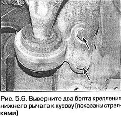
6. Unscrew the two bolts securing the rear support of the lower arm to the body (Fig. 5.6).
7. Loosen the nut on the inner lower arm joint and remove the lower arm from under the car. Keep in mind that the joint may have a tight fit in the subframe. In this case, knock out the joint.
Repair
8. Thoroughly clean the lower arm and the surfaces in the area of its supports, removing all dirt and, if necessary, anti-corrosion coating. Then inspect the arm for cracks, deformations or other signs of damage, paying particular attention to the support bushings and ball joint. If it is necessary to replace the support bushings or ball joint, the lower arm must be handed over to the dealer or a specially equipped auto station. To press out the bushings or ball joint and install new elements, a hydraulic press and special spacer bushings are required.
Installation
9. Before installation, use a tap to clean the threaded hole for the tie bolt of the steering knuckle clamp, which secures the knuckle to the strut.
If you don't have the appropriate tap, you can clean the threaded holes using an old bolt by sawing a groove in it across the threads.
10. Make sure the ball joint pins and holes are clean and dry, then reinstall the lower arm.
11. Insert the inner joint pin into the subframe and align the ball joint pin with the steering knuckle. If necessary, press in the ball joint pin using a jack installed under the lower arm.
12. Screw the new nut onto the inner joint pin and tighten it to the specified torque.
13. Screw on the new ball joint nut and tighten it to the specified torque.
14. Screw in the lower arm rear support mounting bolts and tighten them to the required torque.
15. On models with axle load sensors, install the sensor link bracket to the lower arm and tighten the mounting nut securely.
16. Install the crossbar under the vehicle and tighten the mounting bolts to the required torque.
17. Install the engine crankcase guard.
18. Install the wheel, lower the vehicle to the ground and tighten the wheel mounting bolts to the specified torque.
You can read the original on the website: BMWman.ru
This article is available at russian, bulgarian, belarusian, ukrainian, serbian, croatian, romanian, polish, slovak, hungarian
Article verified: Ilyinsky Matvey
Share information:
Previous articles
БМВ E46: Wheel suspension
Next articles
Similar articles on other types of BMW cars:
Removal and installation the front suspension strut assembly BMW 5 Series E28 (1981-1988)
Removal and installation the suspension arm BMW 5 Series E12 (1972-1981)
Front suspension — removal and installation BMW 7 Series E32 (1986-1994)
Removal and installation the airbag system module in the left or… BMW X3 E83 (2003-2010)
Removal and installation the lower luggage door lock bracket BMW X5 E53 (1999-2006)
Link in different formats to this page
Visitor comments
No comments yet
- General information
- Manual
- Maintenance
- Power unit
- Engine repair
- Cooling system
- Power system (gasoline)
- Injection system (gasoline)
- Fuel system (diesel)
- Exhaust system
- Ignition system
- Charge and launch systems
- Transmission
- Car gearbox
- Clutch and drive shafts
- Chassis
- Brake system
- Suspension front and rear
- Steering
- Body
- Body care and repair
- Exterior
- Interior
- Electrical equipment
- Troubleshooting
- Lighting and signaling
- Equipment and devices
- Heater and air conditioner
- Electrical circuits
- General information
- Manual
- Repair on the road
- Weekly checks
- Maintenance
- Troubleshooting
- Power unit
- 4 cylinder engines
- 6 cylinder engines
- Engine overhaul
- Cooling and heating
- Fuel and exhaust system
- Starting and charging system
- Ignition system
- Transmission
- Clutch
- Mechanical gearbox
- Automatic gearbox
- Cardan and drive shafts
- Chassis
- Brake system
- Wheel suspension
- Steering
- Body
- Exterior
- Interior
- Electrical equipment
- Equipment and devices
- Electrical circuits
- General information
- Maintenance
- Power unit
- Engine repair
- Cooling system
- Ignition system
- Supply system
- Fuel injection system
- Exhaust system
- Transmission
- Clutch
- Car gearbox
- Front and rear axle
- Chassis
- Steering
- Brake system
- Body
- Exterior
- Interior
- Electrical equipment
- Heating system
- Equipment and devices
- Power devices
- Electrical circuits
- Power unit
- M10/M20 engine
- M40 engine
- Ignition system
- Lubrication system
- Cooling system
- Supply system
- Fuel injection
- Exhaust system
- Transmission
- Clutch
- Manual gearbox
- Front axle
- Rear axle
- Chassis
- Steering
- Brake system
- Body
- Exterior
- Interior
- Electrical equipment
- Heating system
- Equipment and devices
- Electrical circuits
- General information
- Specifications
- Operation and maintenance
- 4-cylinder engine
- Engine repair
- Cooling and lubrication system
- Supply system
- Ignition system
- 6-cylinder engine
- Engine repair
- Cooling and lubrication system
- Supply system
- Fuel injection system
- Ignition system
- Transmission
- Clutch
- 4-speed manual gearbox
- 5-speed manual gearbox
- Automatic gearbox
- Cardan and rear axle
- Chassis
- Steering
- Front suspension
- Rear suspension
- Brake system
- Electrical equipment
- Equipment and devices
- Electrical circuits