
- Home
- BMW 3 Series
- E46
- Electrical equipment
- Equipment and devices
- External lighting devices — removal and installation
External lighting devices — removal and installation (BMW 3 Series E46)
Headlight
1. Remove the appropriate direction indicator (see item 12).
2. Carefully remove the headlight washer nozzle (if it exists) from the bottom of the headlight trim and pull the hose out until it stops. Use a jerk to disconnect the nozzle from the hose.
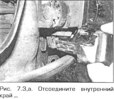
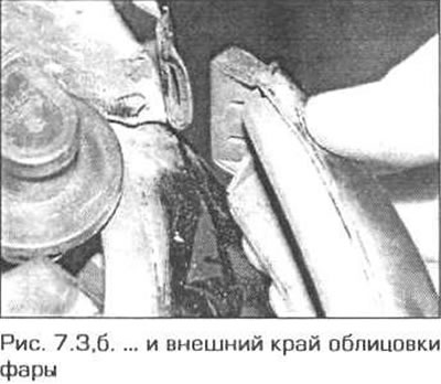
3. Disconnect the inner edge of the headlight trim, then lightly press the trim from top to bottom and disconnect the central clips, then disconnect the outer edge of the trim from the front wing (fig. 7.3 a, b). If necessary, you can remove the headlight lens by disconnecting the clips located around the circumference of the lens.
4. Disconnect all electrical wiring connectors from the rear of the headlight, remembering their location.
5. Each headlight is secured with four screws: two hex head screws and two slotted head screws. Remove the headlight mounting screws (Fig. 7.5).
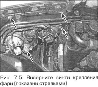
Note: When removing the screws, do not allow the plastic fasteners to rotate. If necessary, hold the fasteners with an open-end wrench.
6. Remove the headlight from the vehicle.
7. Installation is performed in the reverse order of removal. Lightly tighten the headlight mounting screws and check the position of the headlight relative to the bumper and hood. After the headlight is finally installed, securely tighten the mounting screws and check the headlight adjustment (see paragraph 8).
Xenon headlight control unit
8. Remove the appropriate headlight (see above).
9. Unscrew the two mounting screws, move the control unit to the rear side of the headlight and remove the unit (Fig. 5.10).
10. If necessary, remove the control unit from the bracket by unscrewing the two mounting screws.
11. Installation is carried out in the reverse order of removal.
Front direction indicators
12. Insert a screwdriver into the hole of the corresponding mudguard in the engine compartment and press down on the block retainer (see Fig. 5.19, a, b). In the "coupe" model, the block is secured with one screw (see fig. 5.19 in). Slide the unit forward and disconnect the electrical wiring connector from it.
13. Installation is performed in the reverse order of removal. Make sure that the retainer securely holds the unit in place.
Side turn signal repeaters
14. Carefully push the side turn signal repeater lens forward. Pull the rear edge of the lens and remove it from the wing (Fig. 5.23). Disconnect the electrical wiring connector from the unit.
15. Installation is carried out in the reverse order of removal.
Front fog lights
"Sedan" and "Tourist" models
16. Using a wooden or plastic tool, carefully remove the headlight from the bumper, starting from the inner corner (Fig. 5.26). Disconnect the electrical wiring connector from the headlight.
17. Installation is carried out in the reverse order of removal.
Model "coupe"
18. Remove the clips and remove the fog light trim from the bumper (Fig. 5.31).
19. Remove the screws and headlight. Disconnect the electrical wiring connector from the headlight
20. Installation is carried out in the reverse order of removal.
Rear light unit
Body-mounted lights - "sedan" and "coupe" models
21. Inside the luggage compartment, release the clamp (in models manufactured before September 2001) or remove the retainer (in models produced since October 2001) and remove the cartridge block from the rear light (see fig. 5.35 a, b).
22. Remove the fasteners and partially remove the side trim of the luggage compartment in the area of the rear lights (see chapter 11, paragraph 27).
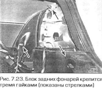
23. Unscrew the three nuts and remove the light from the wing (Fig. 7.23).
24. Installation is carried out in the reverse order of removal.
Body mounted lights - "tourist" model
25. To access the lamp holders, turn the flap 8 in the luggage compartment. To facilitate access to the left lamp, remove the warning triangle.
26. Disconnect the retainer and lift the cartridge block slightly (see fig. 5.39).
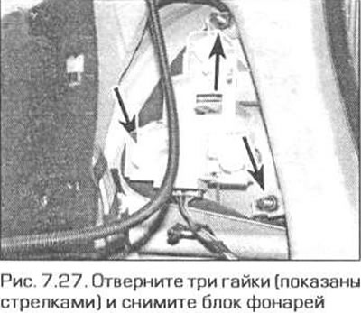
27. Unscrew the three nuts and remove the light (Fig. 7.27)
28. Installation is carried out in the reverse order of removal.
Trunk-mounted lights - "sedan" and "coupe" models
29. Remove the two fasteners and bend the part of the trunk lid trim away from the light (Fig. 5.42).
30. Press the lock and remove the cartridge block from the trunk lid (see fig. 5.43).
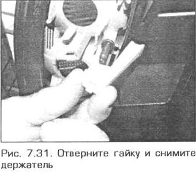
31. Unscrew the nut, remove the holder, then remove the lamp (Fig. 7.31). Note that the edge of the lamp goes around the corner of the trunk lid.
32. Installation is carried out in the reverse order of removal.
Lights mounted on the tailgate - "tourist" model
33. Carefully disconnect the luggage compartment light from the luggage compartment door trim. Disconnect the electrical wiring connector from the unit.
34. Bend back a small piece of the facing from the top (see fig. 5.47).
35. Remove the two screws located in the upper corner and carefully release the panel clips (see fig. 5.48). Remove the panel.
36. Disconnect the electrical wiring connector from the rear light assembly, press the retainer and remove the socket assembly (see fig. 5.49).
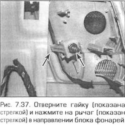
37. Loosen the fastening nut, press the locking lever towards the light unit and remove the light unit (Fig. 7.37).
38. Installation is carried out in the reverse order of removal.
License plate light
39. Using a small screwdriver, carefully pry the lens out of the trunk lid/tailgate (see fig. 5.55). Disconnect the electrical wiring connector from the unit.
40. Installation is carried out in the reverse order of removal.
Electric headlight adjustment drives
41. Remove the headlight lens (see pp. 1-3).
42. Remove both sockets from the back of the headlight (see paragraph 5).
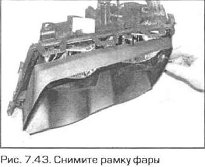
43. Carefully pull the headlight frame forward (Fig. 7.43).
44. Remove the rubber seals of the sockets from the rear of the headlight.
45. Mark the position of the central adjustment wheel, then turn it clockwise, counting the number of revolutions (maybe 20-30 revolutions), until the top of the insert is visible. Then disconnect the outer part of the regulator from the insert. Carefully disconnect the electric drive rod from the back of the insert. Remove the insert from the headlight.
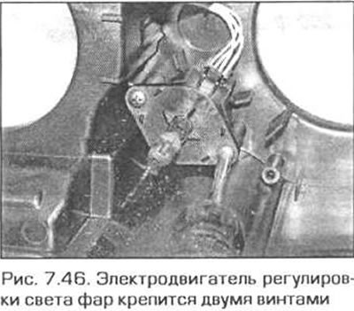
46. Loosen the mounting screws, disconnect the electrical wiring connector and remove the electric drive (Fig. 7.46).
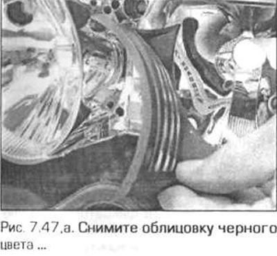
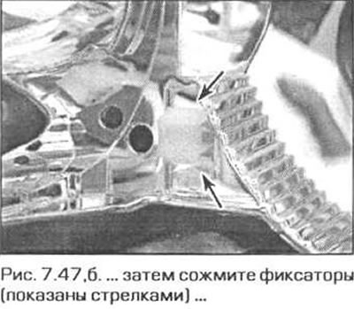
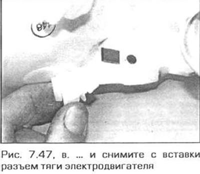
47. When installing the insert, remove the clips. Then remove the black trim from the insert. After that, squeeze the two clips and remove the traction socket from the insert (fig. 7.47, a-c). Do not reinstall the black trim yet.
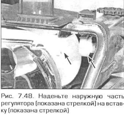
48. Place the socket on the electric drive rod. Place the outer part on the insert and align it with the center of the hole in the headlight housing. Then screw the regulator back into place. Place the socket of the electric drive rod on the insert and push it into place (Fig. 7.48). Install the black trim.
49. After finishing work, check and, if necessary, adjust the headlights.
This article is available at russian, bulgarian, belarusian, ukrainian, serbian, croatian, romanian, polish, slovak, hungarian
Article verified: Ilyinsky Matvey
Share information:
Previous articles
БМВ E46: Equipment and devices
Next articles
Similar articles on other types of BMW cars:
Removal and installation the oil pan BMW 5 Series E12 (1972-1981)
Removal and installation of other outdoor lighting devices BMW 7 Series E38 (1994-2001)
Cylinder Head Cover — Removal and Installation BMW 7 Series E32 (1986-1994)
Pistons — removal and installation BMW X3 E83 (2003-2010)
External body lighting BMW X5 E53 (1999-2006)
Link in different formats to this page
Visitor comments
No comments yet
- General information
- Manual
- Maintenance
- Power unit
- Engine repair
- Cooling system
- Power system (gasoline)
- Injection system (gasoline)
- Fuel system (diesel)
- Exhaust system
- Ignition system
- Charge and launch systems
- Transmission
- Car gearbox
- Clutch and drive shafts
- Chassis
- Brake system
- Suspension front and rear
- Steering
- Body
- Body care and repair
- Exterior
- Interior
- Electrical equipment
- Troubleshooting
- Lighting and signaling
- Equipment and devices
- Heater and air conditioner
- Electrical circuits
- General information
- Manual
- Repair on the road
- Weekly checks
- Maintenance
- Troubleshooting
- Power unit
- 4 cylinder engines
- 6 cylinder engines
- Engine overhaul
- Cooling and heating
- Fuel and exhaust system
- Starting and charging system
- Ignition system
- Transmission
- Clutch
- Mechanical gearbox
- Automatic gearbox
- Cardan and drive shafts
- Chassis
- Brake system
- Wheel suspension
- Steering
- Body
- Exterior
- Interior
- Electrical equipment
- Equipment and devices
- Electrical circuits
- General information
- Maintenance
- Power unit
- Engine repair
- Cooling system
- Ignition system
- Supply system
- Fuel injection system
- Exhaust system
- Transmission
- Clutch
- Car gearbox
- Front and rear axle
- Chassis
- Steering
- Brake system
- Body
- Exterior
- Interior
- Electrical equipment
- Heating system
- Equipment and devices
- Power devices
- Electrical circuits
- Power unit
- M10/M20 engine
- M40 engine
- Ignition system
- Lubrication system
- Cooling system
- Supply system
- Fuel injection
- Exhaust system
- Transmission
- Clutch
- Manual gearbox
- Front axle
- Rear axle
- Chassis
- Steering
- Brake system
- Body
- Exterior
- Interior
- Electrical equipment
- Heating system
- Equipment and devices
- Electrical circuits
- General information
- Specifications
- Operation and maintenance
- 4-cylinder engine
- Engine repair
- Cooling and lubrication system
- Supply system
- Ignition system
- 6-cylinder engine
- Engine repair
- Cooling and lubrication system
- Supply system
- Fuel injection system
- Ignition system
- Transmission
- Clutch
- 4-speed manual gearbox
- 5-speed manual gearbox
- Automatic gearbox
- Cardan and rear axle
- Chassis
- Steering
- Front suspension
- Rear suspension
- Brake system
- Electrical equipment
- Equipment and devices
- Electrical circuits