
Table of contents: Ignition/steering column lock switch ↓ Multi-function switch on the…↓ Headlight switch ↓ Hazard warning switch and central…↓ Electric window switches ↓ Exterior mirror switches ↓ Cruise control switch on the clutch…↓ Rear Window Defogger Switch ↓ Heater Fan Motor Switch ↓ Air conditioning switches ↓ Switches for seat heaters, rear…↓ Parking brake warning light switch ↓ Brake light switch ↓ Interior Light Switches ↓ Steering wheel switches ↓ Sunroof drive switch ↓
- Home
- BMW 3 Series
- E46
- Electrical equipment
- Equipment and devices
- Switches — removal and installation
Switches — removal and installation (BMW 3 Series E46)
Note: Before removing the switch, you must disconnect the wire from the negative battery terminal (see chapter 5A) and reconnect it after installing the switch in place.
Ignition/steering column lock switch
1. See Chapter 10.
Multi-function switch on the steering column
2. Place the steering column in the fully extended and lowered position. Remove the steering wheel (see chapter 10).
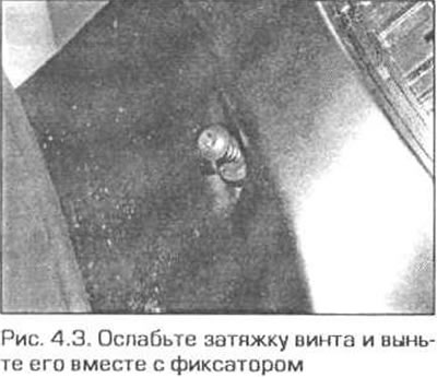
3. Loosen the screw securing the upper part of the steering column trim and remove the screw together with the retainer. Lightly press the edges of the trim together, lift the end adjacent to the steering wheel, then detach the other end of the trim (Fig. 4.3).
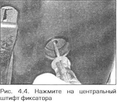
4. Place the steering column in the fully raised and extended position. Using a small screwdriver, press in the center pins, then remove the two retaining clips of the lower steering column trim. Gently squeeze the edges of the upper trim and remove the lower trim (Fig. 4.4).
5. Disconnect the electrical connectors from the airbag unit, windshield wiper switches and turn signal switches.
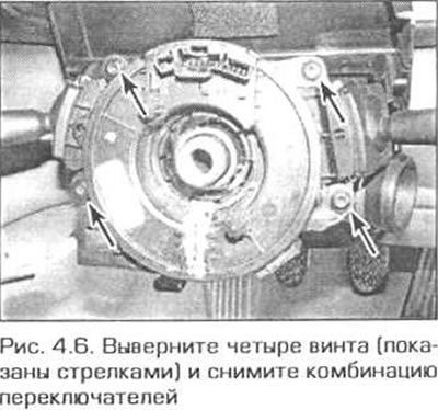
6. Remove the four screws and the switch cluster from the steering column (Fig. 4.6).
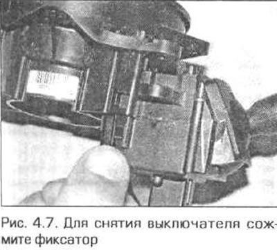
7. If necessary, press the latches and remove the switches from the unit (Fig. 4.7).
8. Installation is performed in the reverse order of removal. Make sure that the wiring is routed correctly.
Headlight switch
9. Using a plastic spatula, carefully remove the decorative trim panel on the driver's side (above the switch). Be careful not to damage the front panel.
10. Open the glove box on the driver's side, remove the two screws in the upper corners and remove the glove box from the front panel (for more information on removing the glove box, see chapter 11, paragraph 27).
11. Remove the two screws located above the switch, lift the switch slightly, remove the top edge of the switch. Then remove the switch from the front panel. Lift the retainer and disconnect the wiring connector from the switch (fig. 4.11, a, b). The switch is a non-separable unit.
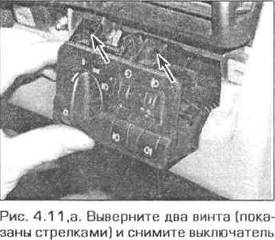
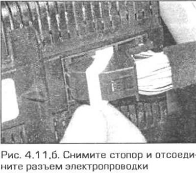
12. Installation is carried out in the reverse order of removal.
Hazard warning switch and central locking switch
13. On manual transmission models, carefully remove the gearshift boot from the center console and screw it onto the gearshift lever.
14. On models with automatic transmission, carefully remove the selector boot and surrounding trim.
15. Remove the box/ashtray from the rear of the center console, then remove the four screws (two screws at the front and two at the rear) securing the center console (see chapter 11). Lift the gear shift lever trim (or selector).
16. Lift the front end of the rear section of the center console and remove the switch. Disconnect the wiring connector (Fig. 4.16).
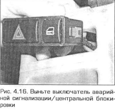
17. Installation is performed in the reverse order of removal.
Electric window switches
18. Remove the gear shift boot (or selector) from the trim and lift it up to access the trim mounting screws (Fig. 4.18). Keep in mind that in models with an automatic transmission, the selector boot is removed together with the trim (see chapter 7B).
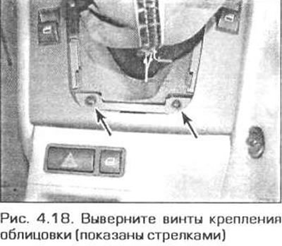
19. Remove the two mounting screws and remove the rear part of the trim.
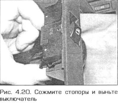
20. Squeeze the stoppers and remove the switches) (Figure 4.20). Disconnect the electrical connector.
21. Installation is carried out in the reverse order of removal.
Exterior mirror switches
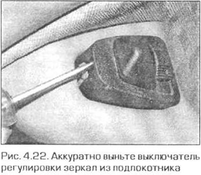
22. Starting from the front edge, carefully remove the switch from the armrest (Fig. 4.22).
23. Disconnect the wiring connector and remove the switch.
24 Installation is carried out in the reverse order of removal.
Cruise control switch on the clutch pedal
25. Remove the mounting screws, then unclip and remove the driver's side lower trim panel. Note the location of the panel and wiring connectors.
26. Disconnect the electrical wiring connector from the switch.
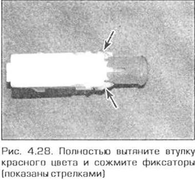
27. Press the clutch pedal and pull out the red switch sleeve.
28. Squeeze the latches and remove the switch (Fig. 4.28).
29. Installation is carried out in the reverse order of removal.
Rear Window Defogger Switch
Models with automatic air conditioning
30. In these models, the switch is part of the control unit and cannot be replaced separately. If the switch is faulty, contact your BMW dealer.
Other models
31. In these models, the switch is part of the printed circuit board of the heater control unit.
32. Remove the heater control panel (see chapter 3).
33. Disconnect the switch wiring connector, release the clips and remove the switch.
34. Installation is performed in the reverse order of removal. Before installing the heater control panel, check the operation of the switch
Heater Fan Motor Switch
Models with automatic air conditioning
35. In these models, the switch is part of the control unit and cannot be replaced separately. If the switch is faulty, contact your BMW dealer.
Other models
36. Remove the heater control panel (see chapter 3).
37. Loosen the mounting screws, then disconnect the switch from the control panel and remove it.
38. Installation is performed in the reverse order of removal. Before installing the heater control panel, check the operation of the switch.
Air conditioning switches
39. See paragraphs 35-38.
Switches for seat heaters, rear screen drive and traction control system (ASC+T)
40. Remove the storage box from the center console.
41. Disconnect the wiring connector, then squeeze the clips and remove the switch.
42. Installation is carried out in the reverse order of removal.
Parking brake warning light switch
43. To access the parking brake lever, remove the rear section of the center console (see chapter 11).
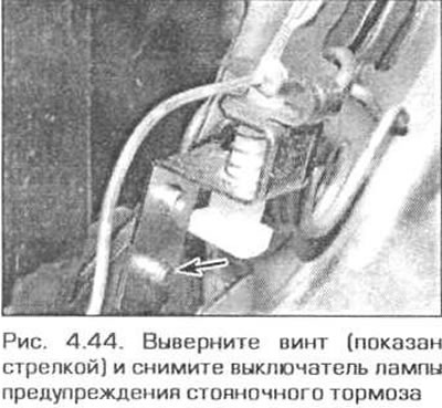
44. Disconnect the electrical wiring connector from the switch, then unscrew the screw and remove the switch (Fig. 4.44).
45. Installation is performed in the reverse order of removal. Before installing the center console, check the operation of the switch. It should operate when the lever is raised 1-2 clicks.
Brake light switch
46. See Chapter 9.
Interior Light Switches
47. The switches for the interior lights are built into the door and trunk lid/tailgate lock units. Removal of the corresponding lock is described in chapter 11.
Steering wheel switches
48. E46 vehicles are equipped with two types of steering wheels: "multifunction" or "sport" steering wheel. To remove the switches, first remove the driver's airbag unit (see paragraph 25), then refer to the appropriate subsection.
Multifunctional steering wheel
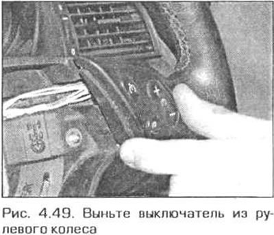
49. Carefully remove the switch from the steering wheel and disconnect the electrical wiring connectors (Fig. 4.49). Note that the horn switch is built into the airbag unit.
Sports steering wheel
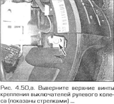
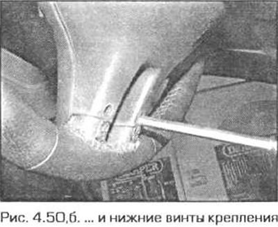
50. Remove four screws (two screws for securing the upper section and two screws for securing the lower section) and disconnect the switch panel from the steering wheel (fig. 4.50, a, b). Disconnect the electrical wiring connector.
Sunroof drive switch
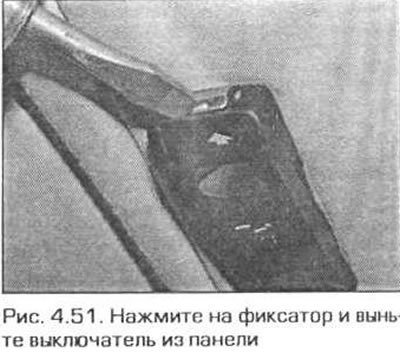
51. Press the release tab at the rear of the switch and remove the switch from the panel (Fig. 4.51).
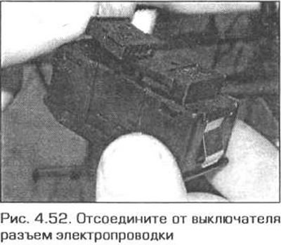
52. Disconnect the electrical wiring connector from the switch, then squeeze the clips and remove the switch (Fig. 4.52).
53. Installation is carried out in the reverse order of removal.
[This article is based on data from the website: «www.bmwman.ru»]
This article is available at russian, bulgarian, belarusian, ukrainian, serbian, croatian, romanian, polish, slovak, hungarian
Article verified: Ilyinsky Matvey
Share information:
Previous articles
БМВ E46: Equipment and devices
Next articles
Similar articles on other types of BMW cars:
Removal and installation switches on the steering column BMW 5 Series E28 (1981-1988)
Removal and installation the oil pan BMW 5 Series E12 (1972-1981)
Removal and installation switches BMW 7 Series E38 (1994-2001)
Cylinder Head Cover — Removal and Installation BMW 7 Series E32 (1986-1994)
Pistons — removal and installation BMW X3 E83 (2003-2010)
Removal and installation the engine BMW X5 E53 (1999-2006)
Link in different formats to this page
Visitor comments
No comments yet
- General information
- Manual
- Maintenance
- Power unit
- Engine repair
- Cooling system
- Power system (gasoline)
- Injection system (gasoline)
- Fuel system (diesel)
- Exhaust system
- Ignition system
- Charge and launch systems
- Transmission
- Car gearbox
- Clutch and drive shafts
- Chassis
- Brake system
- Suspension front and rear
- Steering
- Body
- Body care and repair
- Exterior
- Interior
- Electrical equipment
- Troubleshooting
- Lighting and signaling
- Equipment and devices
- Heater and air conditioner
- Electrical circuits
- General information
- Manual
- Repair on the road
- Weekly checks
- Maintenance
- Troubleshooting
- Power unit
- 4 cylinder engines
- 6 cylinder engines
- Engine overhaul
- Cooling and heating
- Fuel and exhaust system
- Starting and charging system
- Ignition system
- Transmission
- Clutch
- Mechanical gearbox
- Automatic gearbox
- Cardan and drive shafts
- Chassis
- Brake system
- Wheel suspension
- Steering
- Body
- Exterior
- Interior
- Electrical equipment
- Equipment and devices
- Electrical circuits
- General information
- Maintenance
- Power unit
- Engine repair
- Cooling system
- Ignition system
- Supply system
- Fuel injection system
- Exhaust system
- Transmission
- Clutch
- Car gearbox
- Front and rear axle
- Chassis
- Steering
- Brake system
- Body
- Exterior
- Interior
- Electrical equipment
- Heating system
- Equipment and devices
- Power devices
- Electrical circuits
- Power unit
- M10/M20 engine
- M40 engine
- Ignition system
- Lubrication system
- Cooling system
- Supply system
- Fuel injection
- Exhaust system
- Transmission
- Clutch
- Manual gearbox
- Front axle
- Rear axle
- Chassis
- Steering
- Brake system
- Body
- Exterior
- Interior
- Electrical equipment
- Heating system
- Equipment and devices
- Electrical circuits
- General information
- Specifications
- Operation and maintenance
- 4-cylinder engine
- Engine repair
- Cooling and lubrication system
- Supply system
- Ignition system
- 6-cylinder engine
- Engine repair
- Cooling and lubrication system
- Supply system
- Fuel injection system
- Ignition system
- Transmission
- Clutch
- 4-speed manual gearbox
- 5-speed manual gearbox
- Automatic gearbox
- Cardan and rear axle
- Chassis
- Steering
- Front suspension
- Rear suspension
- Brake system
- Electrical equipment
- Equipment and devices
- Electrical circuits